12
IO Modual
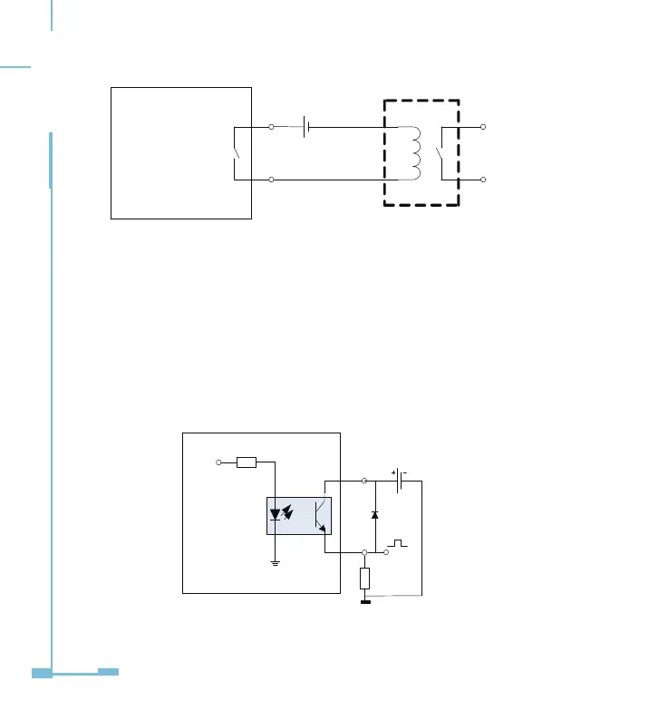
Figure 2-7 schematic diagram of relay output circuit
The wire of relay output should be chosen between AWG22~16 or
0.5~1.3mm
2
.
Wiring of Digital Output Circuit:
There are 2 digital output circuits in AXM-IO2 module. The digital output
circuit can work in alarm state, or work in energy pulse output state.
Digital output circuit form is Photo-MOS. The simplified circuit is as
gure 2-8.
Figure 2-8 schematic diagram of digital output circuit 1
DO
n
DOC
Internal
control node
J
Auxiliary
power supply
Photo-MOS
OUT
IO module
ROn
ROC
mediate relay
Auxiliary
power supply
coil
control
output
 Loading...