14
IO Modual
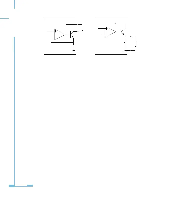
Figure 2-10 schematic diagram of analog output circuit
The Load Capability of Analog Output Circuit:
0 to 20mA mode: the max load resistance is 500Ω.
4 to 20mA mode: the max load resistance is 500Ω.
0 to 5V mode: the max load current is 20mA.
1 to 5V mode: the max load current is 20mA.
Wiring of Analog Input Circuit:
There are 2 analog input circuits in AXM-IO3 modules. The terminals of
analog input circuit are AI1+, AI1- and AI2+, AI2-. The analog input circuit
supplies 4 input modes, including 0 to 20mA mode, 4 to 20mA mode, 0 to
5V mode and 1 to 5V mode.
The simplied circuit is as gure 2-11.
VCC
VO
load
VCC
VO
load
R R2
R1
Current analog output Voltage analog output
AO+
AO- AO+
AO-
 Loading...