EasyManua.ls Logo

Accurex XRRS User Manual

Accurex XRRS
28 pages
To Next Page IconTo Next Page
Page #1 background imageLoading...
Page #1 background image
1
Fire Ready Hood
Installation, Operation and Maintenance Manual
Please read and save these instructions for future reference. Read carefully before attempting to assemble, install,
operate or maintain the product described. Protect yourself and others by observing all safety information. Failure
to comply with instructions could result in personal injury and/or property damage!
WARNING
To reduce the risk of fire, electric shock, or injury
to persons, observe the following:
Use this unit only in the manner intended by the
manufacturer.
Before servicing or cleaning unit, switch power off
at service panel and lock the service disconnecting
means to prevent power from being switched on
accidentally. When the service disconnecting means
cannot be locked, securely fasten a prominent
warning device, such as a tag, to the service panel.
Installation work and electrical wiring must be
done by a qualified person(s) in accordance with all
applicable codes and standards, including fire rated
construction codes and standards.
Sufficient air is needed for proper combustion
and exhausting of gases through the flue
(chimney) of fuel burning equipment to prevent
backdrafting. Follow the heating equipment
manufacturer’s guideline and safety standards such
as those published by the National Fire Protection
Association (NFPA), and the American Society
of Heating, Refrigeration and Air Conditioning
Engineers (ASHRAE), and the local code authorities.
When cutting or drilling into wall or ceiling, do not
damage electrical wiring and other hidden utilities.
To reduce the risk of fire or electric shock, do
not use this range hood with an additional speed
control device.
Ducted fans must always be vented to the
outdoors.
To reduce the risk of fire, use only metal ductwork.
Use with approved wiring only.
This unit must be grounded.
WARNING
To reduce the risk of range top grease fire:
Never leave surface units unattended at high
settings. Boilovers cause smoking and greasy
spillovers that may ignite. Heat oils slowly on low or
medium settings.
Always turn hood ON when cooking at high heat or
when cooking flaming foods.
Clean ventilation fans frequently. Grease should not
be allowed to accumulate on fan or filter.
Use proper pan size. Always use cookware
appropriate for the size of the surface element.
To reduce the risk of injury to persons in the event
of a range top grease fire, observe the following:*
SMOTHER FLAMES with a close-fitting lid, cookie
sheet, or metal tray, then turn off the burner. BE
CAREFUL TO PREVENT BURNS. If the flames do
not go out immediately, EVACUATE AND CALL THE
FIRE DEPARTMENT.
NEVER PICK UP A FLAMING PAN. You may be
burned.
DO NOT USE WATER, including wet dishcloths or
towels - violent steam explosion will result.
* Based on “Kitchen Fire Safety Tips” published by
NFPA.
Listed to UL 300A Standard
REPORT #1293
Model XRRS
Fire Ready Hood
Question and Answer IconNeed help?

Do you have a question about the Accurex XRRS and is the answer not in the manual?

Accurex XRRS Specifications

General IconGeneral
BrandAccurex
ModelXRRS
CategoryVentilation Hood
LanguageEnglish

Summary

Receiving, Unpacking, Handling & Storage

Receiving the Product

Check all items upon receipt and inspect for shipping damage before accepting delivery.

Unpacking and Verifying Parts

Verify all required parts and quantities received. Report any missing items to the local representative.

Handling the Unit

Handle the unit to prevent scratching or chipping the coating, as damaged finish reduces corrosion resistance.

Storage Recommendations

Store units indoors in a low humidity atmosphere between 30°F and 110°F for optimal preservation.

Model Number Code

Exploded View

Parts Checklist

Sample Installations

Preparing the Install Location

Mounting Bracket Placement

Center the mounting bracket over the range; use page 7 for specific mounting points and access holes.

Ductwork Specifications

Select ductwork and fittings carefully to ensure static pressure aligns with fan parameters for optimal airflow.

Static Pressure Testing

Measure static pressure using a magnehelic gauge; a reading of 0.45 to 0.85 inches wg is required.

Fans

Accessories

Installation

Installation Heights

Details on minimum and maximum installation heights for XRRS-30 and XRRS-36 models.

Mounting Bracket Details

Provides center notches, critical mounting points, and access points for junction box connections.

Mounting Bracket for NFPA Installation

Specific mounting bracket dimensions and hole locations for NFPA compliant installations.

Installing Hood onto Mounting Bracket

Securing the Hood and Safety Cable

Steps to lift, seat, and secure the hood to the mounting bracket, including safety cable attachment.

Connecting Power and Arming System

Connect the male plug to the female plug and arm the system by removing safety pin and key.

Installing Fan (if applicable)

Inline Fan Installation

Instructions for installing inline fans vertically in ductwork, emphasizing sealing and minimizing bends.

Wall Mounted Fan Installation

Steps to fasten the fan box to an external wall and attach ductwork using sealant for air leakage prevention.

Range Element Disconnect Installation

Gas Disconnect Valve Installation

Details on installing the 3/4-inch NPT gas solenoid valve, noting IN/OUT ends for gas flow direction.

Electrical Disconnect Box Installation

Instructions for cutting a drywall hole, running wiring, and making connections for the relay box.

Installing Accessories

ClockBox Installation

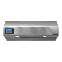
Details on mounting the ClockBox controller and touchscreen user-interface remotely near the appliance.

Manual Pull Station Installation

Step-by-step guide for installing the pull station, including conduit, cable, and pull face attachment.

Electrical Installation

Main Control Power Wiring

Determine mounting locations, run factory-provided wire, and connect to a 15 amp rated circuit.

Fire Alarm System Wiring

Accommodations for fire alarm system wires need to be made during electrical installation.

Optional Component Installation

Fan, ClockBox, and ADA Switch Setup

Installation details for optional fans, ClockBox system, and ADA remote switches.

Fire Alarm System Connections

Connect alarm outputs to controller and wire fire alarm switch to controller for system integration.

Wiring Diagram

ClockBox Wiring Diagram

Operation - How it Works

System Features

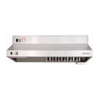
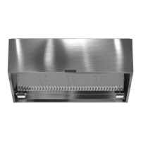
Describes the XRRS as a ventilation hood with fire suppression, controller, alarms, and basic controls.

Environmental Monitoring / Pre-Suppression Functions

Controller monitors temperature with thermostats, activating fan at 150°F and shutting off stove at 190°F.

Accessing the Internal Components

Moving Unit to Service Position

Steps to tilt the unit down into a service position for access to components and extinguisher tank.

Safety Precautions During Servicing

Cautionary notes regarding potential discharge, high pressure, and electrical shock hazards when working on the unit.

ClockBox Operation and Navigation

Basic Timer Functions

Instructions for starting, pausing, stopping, and resetting the 2-hour timer on the ClockBox.

Password Management

Details on accessing hidden menus, modifying timer values, and managing passwords with the factory preset.

Test Tank and Demonstration

Cutting Test Links

Procedure to simulate actuation by replacing a fusible link with a test link and cutting it.

Manual Pull Kit Actuation

How to actuate the system using the manual pull station by pulling the handle.

Controller Schematic

Controller Inputs and Outputs

Explains LED indicators for inputs (X) and outputs (Y) and their corresponding scenarios and states.

Alarm Connections and Service Switch

Details on connecting alarm outputs and the function of the service switch for deactivating alarms.

Self-Monitoring System

Low Pressure Test

Procedure to test the low pressure function by unplugging the pressure switch connection.

High Temperature Test

How to test the high temperature switch by unplugging a wire terminal or using a heat gun.

Alarm Discharge Switch Test

Check continuity of normally open and closed contacts for the alarm discharge switch.

After an Actuation

Clean-Up Procedures

Steps for cleaning surfaces after discharge, emphasizing safety and proper disposal of affected items.

Determine Cause of Discharge

Investigate potential causes of discharge, such as fire, manual pull, or aged fusible links.

How to Reset the Suppression System

Step-by-step guide to reset detection system, replace fusible links, and simulate actuation for testing.

Recharge Tank

Instructions for recharging the tank with nitrogen after a discharge or inspection.

Resetting Gas Shut-Off Valve

Resetting Electrical Relay Shut-Off

Maintaining the System

Cleaning the Hood

Guide for cleaning grease build-up, mentioning dishwasher-safe parts and replaceable filters.

Inspect the Nozzle Caps

Instructions for inspecting and cleaning nozzle caps, and replacing them if necessary.

Inspect Fusible Link System

Periodic inspection of fusible links, pulleys, and cable to ensure readiness for fire events.

Lighting Replacement

Instructions for replacing the 60-watt incandescent light bulb.

Removing the Extinguisher Tank

Steps to lower the hood, insert safety pin, and disconnect components to remove the extinguisher tank.

Recommended Service and Recertification Schedule

Replacement Parts

Maintenance Log

Our Commitment

Related product manuals