Installation & Operation Manual - Model AVC6000
Contents of this Manual are Subject to Change Without Notification Page 15
SECTION 5 – WIRING
5.1 AVC6000 Control Module
5.2 Wiring Instructions
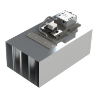
1. Remove Control Module Cover and insert cables through strain relief fitting into enclosure.
2. Remove terminal block plug(s) and connect wires to the appropriate terminals.
3. Secure terminal screws and reinstall plug(s).
4. Insert the ratcheting strain relief over cable(s) and push down until snug.
5. Reinstall cover and secure thumb screw.
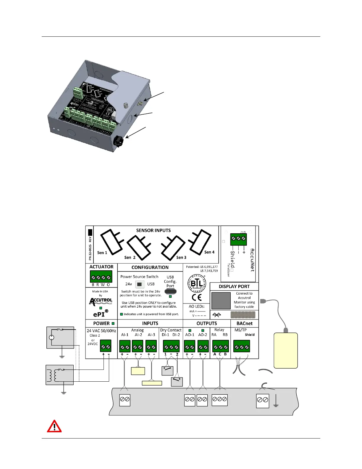
5.3 Control Module Wiring Diagram: Connections will vary based on application.
OR
Analog Output
Analog Inputs
DDC
Controller
Digital Inputs
DI DI
Gnd
MS/TP
BACnet
24 vAC
24 vDC
+
Gnd
Shield
+
-
Factory
Supplied
Cable
SW 1
SW 2
Accutrol
VSS
Accutrol HSS
+
Gnd
+
Gnd
EIA 485
BACnet
MS/TP Bus
From
Previous
Device
To Next
Device
+ -
+ -
Accutrol
Monitor or
Remote
Com Port
CAUTION: Maintain polarity if power source is used for multiple devices, otherwise
equipment may be damaged.
Cable tie loop provided for remote
monitor cable strain relief
Cable entry with ratcheting strain relief fitting
Note: If a conduit connection is required, the strain relief
fitting and bushing can be removed and replaced with a
.875 (22mm) conduit fitting. (Provided by Others)
Entry for remote monitor cable connection
 Loading...