Chapter 5 56
Introduction of Connectors and Headers
System Board Jumper Setting
System Board Header Setting
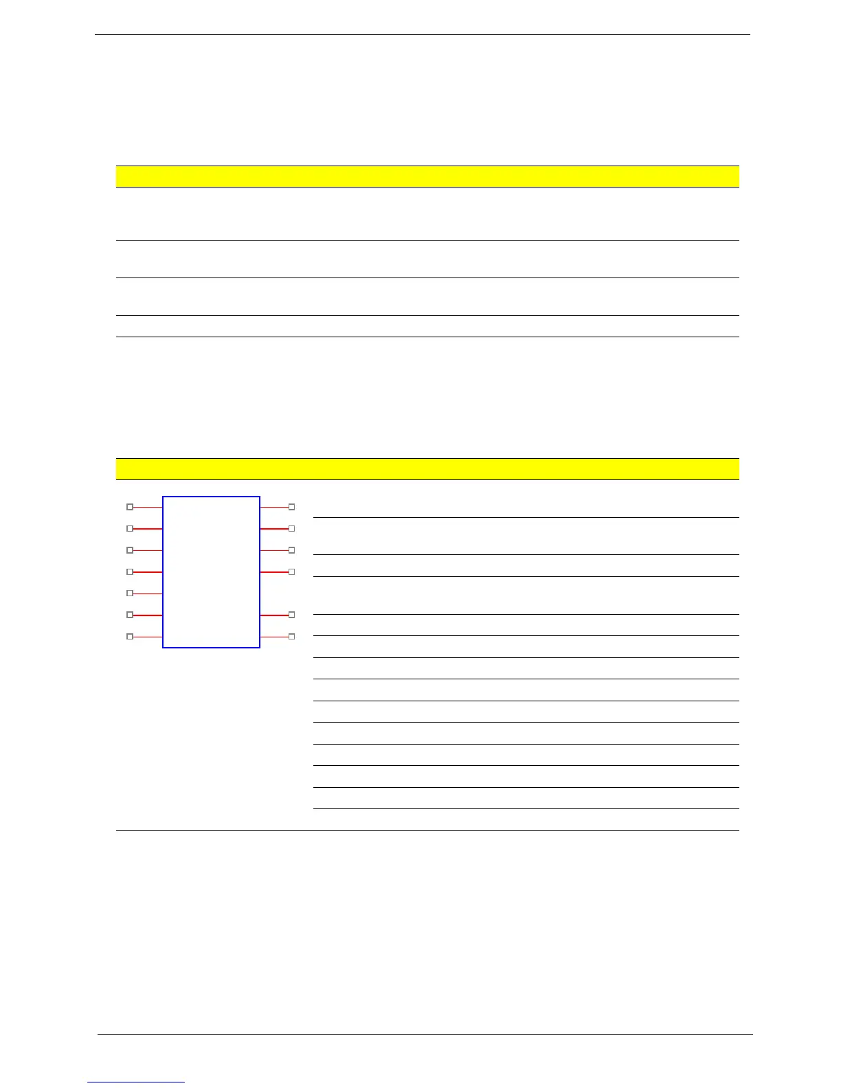
Front Panel
Features Default Setting Remark (color and other)
Intruder pin (1*2) & default
setting
No active Short will have the warning
message The case has been
opened, press F1 to continue.
BIOS_SEL1 (1*2) & default
setting
Enable SPI
Clear CMOS (1*3) & default
setting
2-3: normal (default)
OBR (1*2) & default setting No active
# Pin Definition Description
1 5V_SYS Hard disk LED pull-up (330 ohm) to
5V_SYS
2 GPIO_GRN_HDR_R Pull-up (330 ohm) to 5V_SB_SYS and
connect To to SIO GPIO
3 HDD_LED_R Hard disk active LED
4 GPIO_YLW_HDR_R Pull-up (330 ohm) to 5V_SB_SYS and
connect to SIO GPIO
5 GND Reset button
6 PSIN Power button
7 ICH_SYS_RSTJ ICH_SYS_RSTJ
8 GND Ground
9 5V_SYS 5V_SYS
10 Key Key
11 NC Reserved
12 GND Ground
13 NC Reserved
14 LAN_ACTJ LAN active LED
Orange1
1
Orange3
3
Blue5
5
Blue7
7
Black9
9
Orange11
11
Green2
2
Red6
6
Red8
8
Green12
12
Green14
14
Green4
4
Orange13
13
FP1
Header_2X7_K10
 Loading...