72 Chapter 5
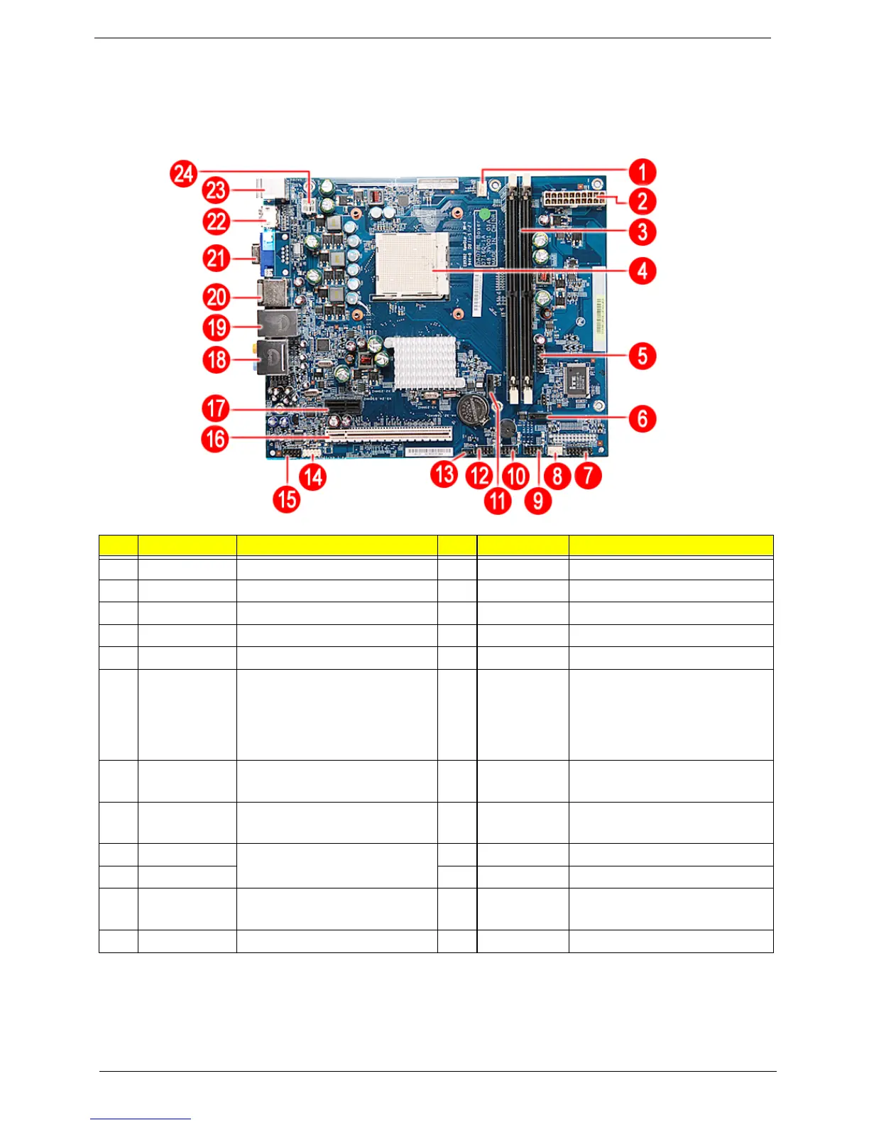
Board Layout
Mainboard
No Code Description No Code Description
1 CPUFAN1 Processor fan cable connector 13 JBIOS1 Clear CMOS jumper
2 PWR2 24-pin ATX power connector 14 FIREH1 IEEE 1394 connector
3 DIMM1 and 2 System memory slots 15 AUDIOF1 Front audio connector
4 UI Processor socket 16 PCIEX16 PCI Express x16 slot
5 DEBUGH1 Debug connector 17 PCIEX1 PCI Express x1 slot
6 SATA2 SATA 2 data cable connector 18 Top: Line-out and line-in jack
and rear speaker and center
speaker jack
Bottom: Microphone port and
S/PDIF port
7 LEDH1 LED cable connector 19 Top: Gigabit LAN port
Bottom: USB ports
8 SYSFAN1 System fan cable connector 20 Top: USB ports
Bottom: eSATA port
9 USBF3 Front USB connectors 21 VGA port
10 USBF2 22 HDMI port
11 SATA1 SATA 1 data cable connector 23 Top: PS2 Mouse Port
Bottom: PS2 Keyboard Port
12 USBF1 Front USB connector 24 PWR1 8-pin ATX power connector
 Loading...