13. INDICATORS UNDER DEVELOPMENT
TRONIC INDICATES THE PROGRAMMING STATUS THROUGH THE MOVEMENT OF THE BLIND
TRONIC IS WAITING TO RECORD A NEW
RADIO COMMAND OR TO REVERSE THE
DIRECTION
TRONIC INDICATES THAT THE DIRECTION
HAS BEEN REVERSED (INSTALLED TO THE
LEFT)
TRONIC INDICATES THAT ALL RADIO
COMMAND CODES HAVE BEEN
CANCELLED
FIG.6
1
0. WARNINGS FOR INSTALLATION
•The Tronic must be installed only by qualified personnel.
• The installer must provide for protection of the device by means of a differential magneto-
thermic breaker (with at least 3 mm distance between the contacts) that ensures detachment of all
poles from the mains in the event of a fault.
•
In the event of a fault, the wiring supplied with the device must be replaced by the manufacturer or
by qualified personnel.
11. TECHNICAL CHARACTERISTICS
Power supply: 230 V AC
Relay contact rating: 10 A
Receiver sensitivity – 105 dBm for S/N = 17 dB with carrier modulation 100 %.
Power supply to external push button: 24 V DC
Motor working time: 120 s. The Tronic interrupts movement of the gearmotor after about 120 s of continuous
operation. This is to prevent the motor heating if, for example, the limit switch fails to function properly
TRONIC conforms to Directive 99/05 and that the standards shown in the table have been applied.
Electrical safety Electromagnetic Efficacious use
compatibility of the spectrum
EN 60335-1 ETS 300 683 EN 300 220-3
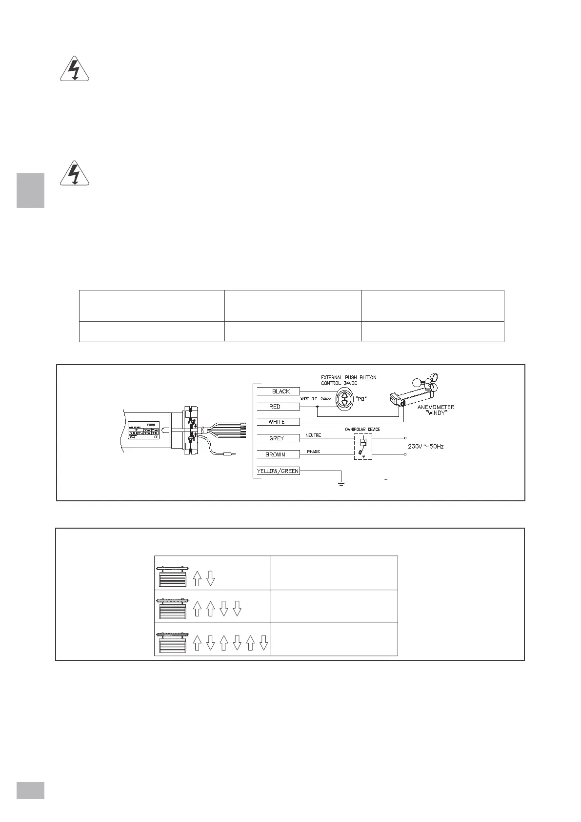
12. ELECTRICAL CONNECTION DIAGRAM
ANEMOMETER