8 9
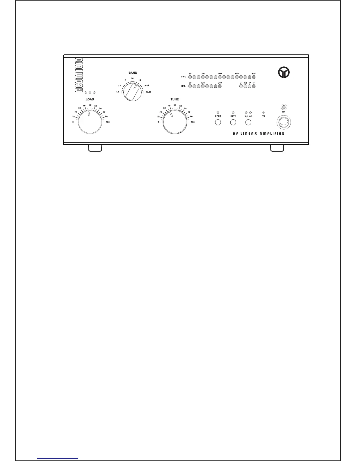
Fig. 3-1 ACOM1010 Display and Control
Note that the upper LED bar-graph always reads peak forward power, except for the service functions
(Section 5-5). The 800 W-scale resolution is 50 W. Note also that levels below 50 W may be not
detected.
The lower LED bar-graph will indicate reflected power up to 240 W. The scale resolution is 30 W.
The OPER button alternatively switches between the operate and standby modes once the amplifier
has completed its 150-second warm-up period. See Section 4-2.
The RTTY button reduces the output power of the amplifier to 500 W. See Section 4-3.
The button labeled A1-A2 (Section 4-4) changes the antenna output to either antenna 1 or antenna 2,
according to the operator’s choice. It is the operator’s responsibility to connect suitable antennas to
the ANT1 and ANT2 connectors on the rear panel of the amplifier.
The red TX LED illuminates whenever the KEY-IN input is keyed (closed to ground), i.e., when the
transceiver goes into the transmit mode. See Section 2-4(d).
The BAND knob controls the band switch, and LOAD and TUNE are used to adjust their respective
variable air capacitors in the amplifier’s output circuit. The settings of these three controls must be changed
at each band change as well as when an antenna is changed. The three LED indicators located above
the knob LOAD are called the “TRI tuning indicator” and they are used to achieve antenna impedance
matching during a re-tune procedure. Please see Section 4-5 for a discussion of the tuning procedure.
CAUTION
To avoid damage not covered by the amplifier’s warranty, do not turn the BAND
switch while transmitting. Switching while transmitting is called “hot switching” and
it will cause irreparable damage to the band switch.
There are three warning LED indicators and one fault LED indicator located in the bar-graphs area.
The following describe the error conditions and the correct responses (except for the service functions
- Section 5-5):
- G1 – when illuminated, a control-grid overload condition exists; reduce the drive power for safe
operation;