6 7
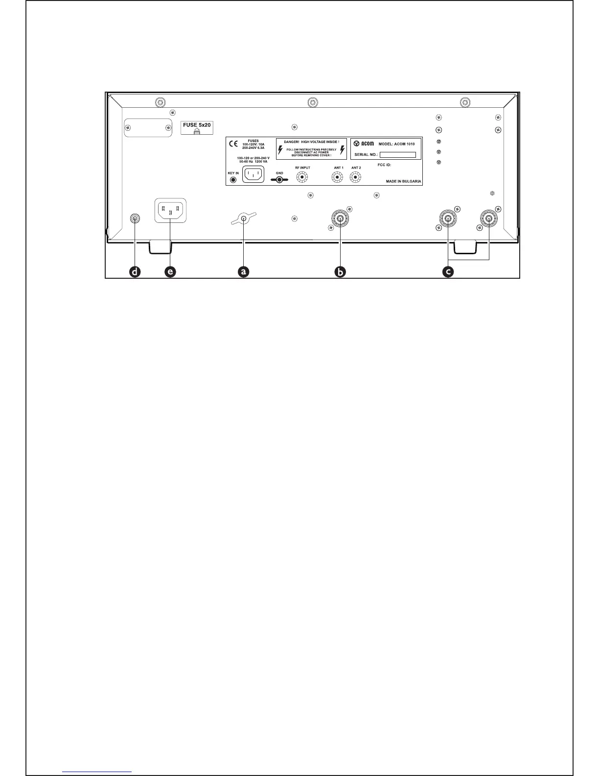
Fig. 2-1 Connections
a) Connect the station’s grounding system to the wing-nut ground stud of the amplifier (on the rear
panel, marked GND in Fig. 2-1).
b) Connect a suitable coaxial cable between the transceiver output to the amplifier (rear panel) RF
INPUT SO-239 connector, using PL-259 connector.
CAUTION
The coaxial cable from the amplifier’s output must be capable of handling the
amplifier’s output power safely, particularly on the 10-meter band. It is suggested
that, at a minimum, RG8X (including RG8MINI, RK50-4-11, RK50-4-13) or, even
better, RG213 (including RK50-7-11) coaxial cable be used.
c) Connect a suitable coaxial cable from the antenna to the appropriate amplifier output (on the rear
panel, marked ANT1 or ANT2), using a PL-259 plug.
d) Run a shielded cable from the “ground on transmit” socket or terminal on your transceiver
to the amplifier rear panel KEY-IN socket. The KEY-IN socket uses a standard RCA phono plug
NOTES
Your amplifier will not work if KEY-IN is not connected properly.
Transceiver producers assign different names to their “ground on transmit” output terminals, e.g., TX-
GND, SEND, T/R-LINE, etc. Some transceivers may require that “ground on transmit” be implemented
by a software command, or by changing the setting of a switch on the rear panel or inside the transceiver.
Check your transceiver’s manual for more information on keying amplifiers.
7