13
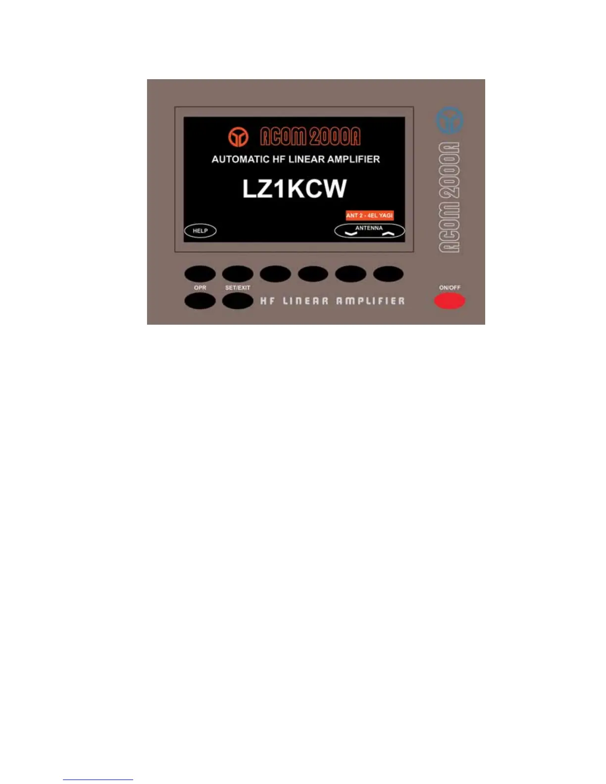
Fig.3-1 Remote Control Unit (RCU)
N O T E
The owner's call sign will be only displayed after it has been programmed into
the RCU. See Section 6-1 for details on programming your callsign.
In this condition, only the RCU is operational, while the amplifier itself is still fully off.
Nevertheless, you have access to the HELP feature (at the left bottom corner, see S5.6) and
you can switch antennas if the ACOM2000S automatic antenna selector and the ACOM2000SW
remote antenna switch are installed. The assigned number and name of the currently used
antenna is shown at the right bottom corner of the display, just above the antenna-change key.
Except for the main power switch on the front panel, the amplier is controlled via the RCU
(see Fig 3-1).The amplier is toggled ON or OFF by pressing the red ON/OFF button. There
are two more “xed function” buttons located at the left bottom – the OPR button which is used
to toggle between OPERATE and STANDBY (STB) modes, and the SET/EXIT button - to enter
and exit the menus.
The six buttons immediately below the bottom of the display are “soft keys” and their function
can vary depending on what the context is at the time. As you explore the various functions of
the amplier, the functions of these buttons are explained in detail.
The control of the amplier is structured in two menus - OFF and MAIN, each having several
sub-menus (g.3-2):