43
ACORN 80 Maintenance & Service Manual
SECTION 7
Dismantling Components
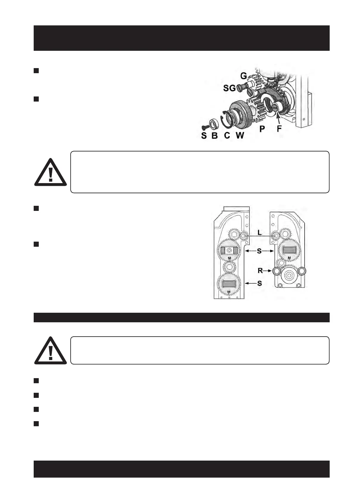
THE GEAR TRAINS OF BOTH BOGIE HALVES ARE CONNECTED BY A LAYSHAFT (L).
IT IS IMPORTANT THAT THE GEARING IS ALIGNED SO THAT ALL SIDE ROLLERS (S) AND
THE RAIL FOLLOWER ASSEMBLY (R) ARE HORIZONTAL AS SHOWN IN THE DIAGRAM.
MARKS (M), STAMPED ONTO THE GEARS TO ASSIST WITH THIS, SHOULD BE POSITIONED
AT BOTTOM DEAD CENTRE.
4 Fit the support wheel (W) and its bearing and secure
with the circlip (C).
5 Fit the backstop (B) and fasten with the
countersunk screw (S).
6
Lightly spray the thrust washers of all gearing side
rollers (S) and the rail follower assembly (R) with the
recommended lubricant.
7 Fasten the front and rear assemblies together with
the three cap head screws (two on the side and one
on the top).
1 Disconnect the Motor and Motor Encoder from the main PCB.
2 Unscrew the four cap screws and remove the gearbox and motor from the rear frame.
3 Apply thread locking compound to the four cap screws and refit gearbox and motor to the rear frame.
4 Reconnect the MAIN MOTOR POSITIVE, MAIN MOTOR NEGATIVE, DRIVE MOTOR ENCODER and
MAIN MOTOR BRAKE to the main PCB terminals.
THE DRIVE MOTOR, ENCODER, MOTOR BRAKE AND GEARBOX MUST BE REPLACED AS A
COMPLETE ASSEMBLY. THEY CAN ONLY BE REMOVED AFTER THE POWER BOGIE HAS BEEN
REMOVED FROM THE CARRIAGE AND THE DRIVE PINION REMOVED.
7.7.4 Drive Motor Removal / Replacement
 Loading...