64
ACORN 80 Maintenance & Service Manual
APPENDIX 7
Levelling and Main Drive Encoder Testing
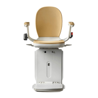
Testing the channels of the encoder
The voltage should alternate between just under 5V
and between 0.25V on both the yellow and green
wires, while turning the levelling motor. The sequence
between the two channels is:
YELLOW GREEN
LOW 0 LOW 0
LOW 0 HIGH 1
HIGH 1 HIGH 1
HIGH 1 LOW 0
Note: This is reversed when turned in the opposite
direction.
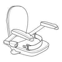
Hand-wind the levelling motor very slowly in either
direction to change the state of the channel under test
from ‘high’ to ‘low’.
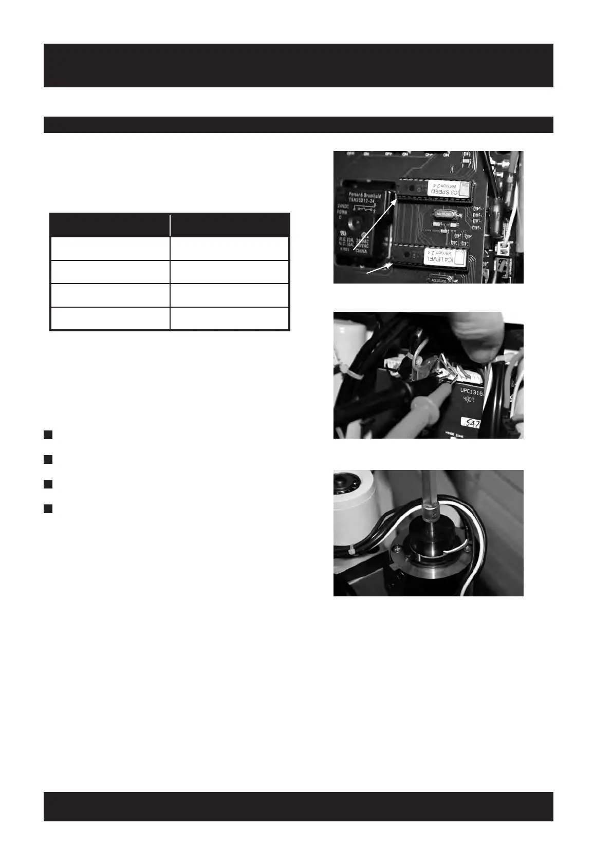
The encoder signals can also be checked on.
The speed chip pins.
PINS 2,3 Main drive encoder.
PINS 4,5 Levelling encoder.
The supply voltage to both speed and
Levelling chips is 5V, and can be measured
On Pin 1.
Repeat the same test for the main drive encoder.
The channels are the WHITE and GREEN wires.
5V
SUPPLY
PIN 1