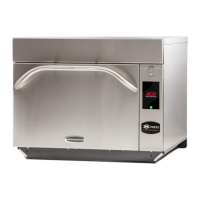
Remove all wires from terminals.
Measure resistance from:
230 to COM..................................................
208 to COM..................................................
230 to Ground ..............................................
208 to Ground ..............................................
Terminal 5 to 6 .............................................
Terminal 4 to Ground...................................
Less than 1
Infinite
Infinite
Less than 1
Approximately
46
Perform service test on low and high speed
to verify operation. Service test procedure
is located in Service Test section.
Disconnect wires from terminals.
Measure resistance across heating
Element 2000 W .......................
Disconnect wires from terminals.
Measure resistance across heating
Element 3000 W .........................
Temp Sensor
(RTD)
(Convection Heater)
Temp Sensor
(Cavity Heater)
Temp Sensor
32F .............................................................
350F ...........................................................
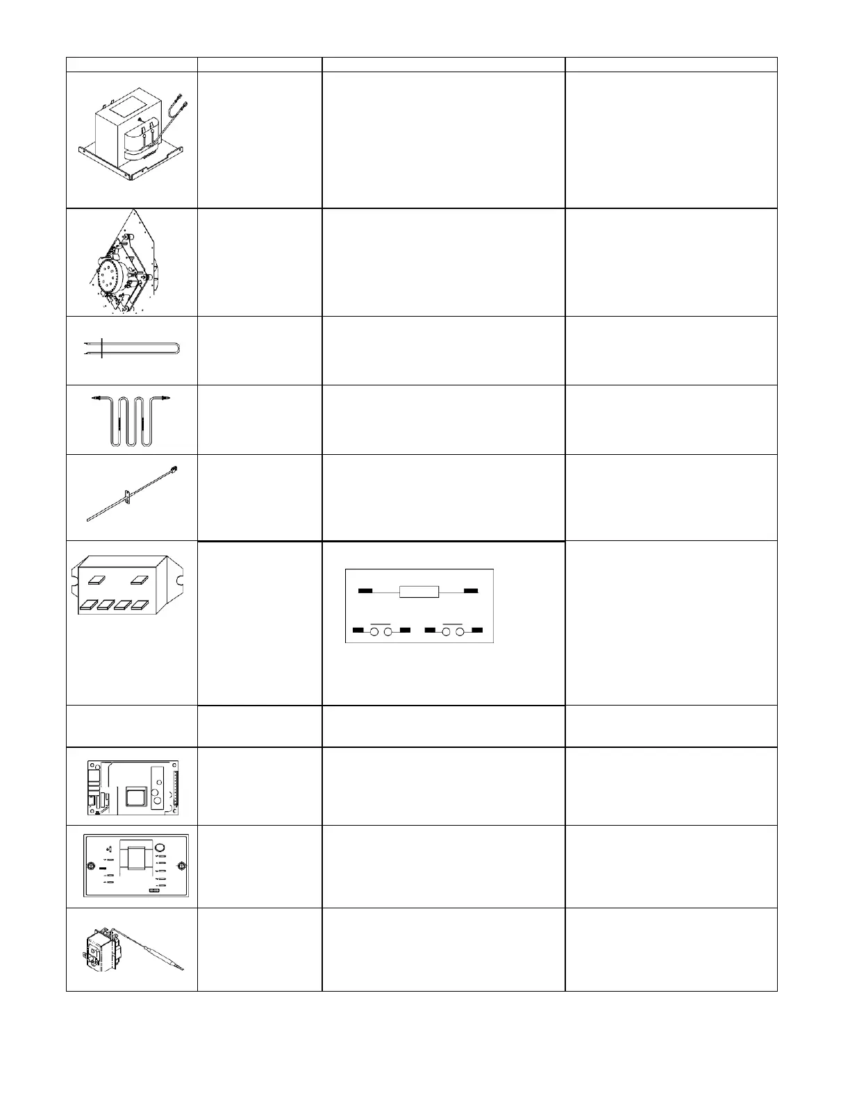
Measure resistance from:
Terminal 0 to terminal 1 (coil) ...........
0 1
2 4
6
8
Approximately 6 to 7 M
Terminal 0 - 1 Line Voltage
Terminal 2 - 6 Line Voltage
Terminal 4 - 8 Line Voltage
NOTE: Analog meter is recommended
for measurement.
NOTE: If using a digital meter it must
contain a battery of 6 volts minimum.
diode in the coil
circuit.
High voltage board
to display module
harness
Test continuity of wires .............................
Power supply board
24 Volt
Input voltage Orange J1-1 to Red J1-3................
Red J2-1 to White J2-6 Power Supply Board
Line Voltage
Approximately 24 vdc
Limiter, Electronic
(some Models)
Orange 9 to Red 10.........................................
Yellow 6 to Yellow 7 ........................................
Line Voltage
Approximately 24 vdc
Thermal Cutout,
Mechanical (some
Models)
Yellow 21 to Yellow 22 ..................................
Indicates continuity. Opens when
above 320C (608F) or Below 0C