1-3
English
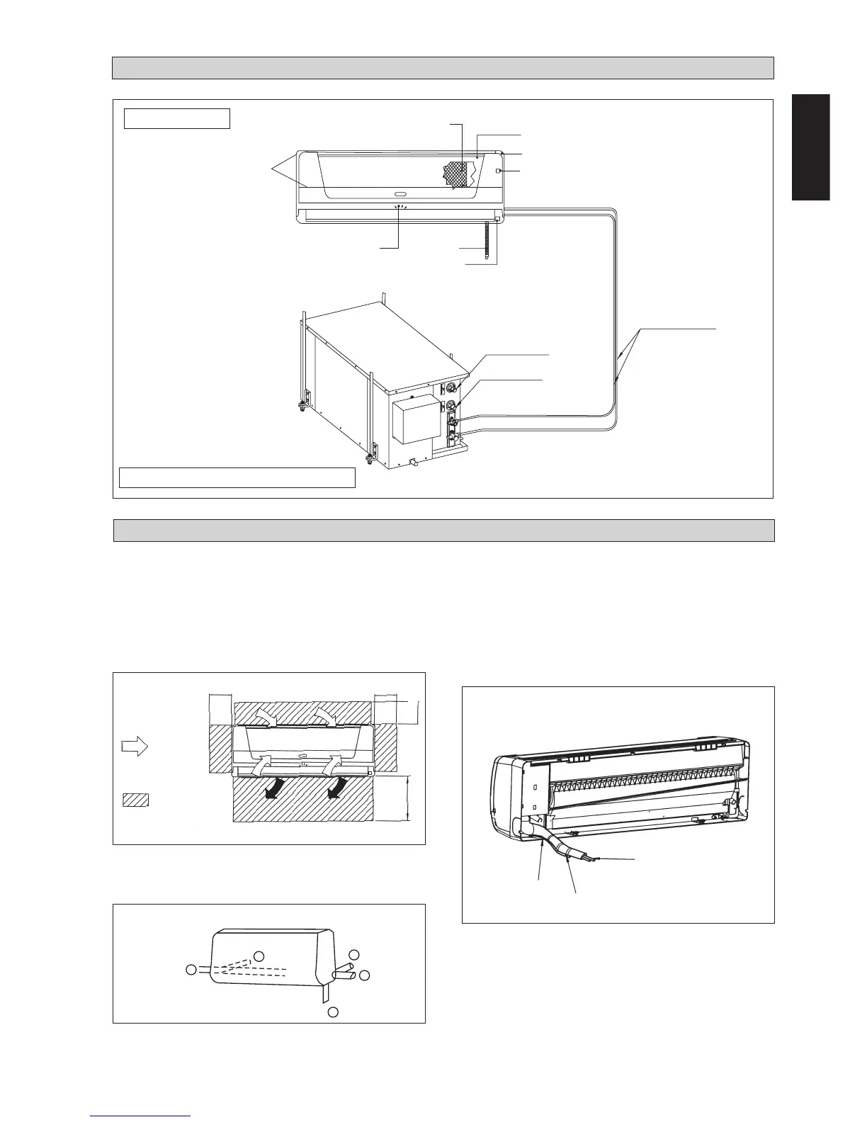
INSTALLATION DIAGRAM
5WMWS-GR
Refrigerant Piping
Return Water
Drain Hose
Signal Receiver
Indicator
Lights
Air Intake
Grille
Back Housing
ON/OFF Switch
Front Frame
Air Filter
Supply Water
Liquid Pipe
Gas Pipe
INSTALLATION OF THE INDOOR UNIT
The indoor unit must be installed in such a way so as to
prevent short circuit of the cool discharged air with the hot
return air. Please follow the installation clearance shown in
the figure. Do not place the indoor unit where there could be
direct sunlight shining on it. Also, this location must be
suitable for piping and drainage, and be away from doors or
windows.
Routing Of Piping
Remove the screw holding the front panel.
Maintenance &
Servicing Space
Air Flow
Direction
Higher Than
Eye Level
The refrigerant piping can be routed to the unit in a
number of ways (left or right from the back of the unit), by
using the cut-out holes on the casing of the unit (see figure).
Bend the pipes carefully to the required position in order to
align it with the holes. For the right hand and rear side out,
hold the bottom of the piping and then position it to the
required direction (see figure). The condensation drain hose
can be taped to the pipes.
1
2
3
4
5
Piping Routing
50.0 mm 50.0 mm
50.0 mm
Right & Rear Side Routing
Drain hose
Fix with vinyl tape
Unit piping
WATER SOURCE HEAT PUMP UNIT