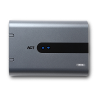
ACTpro 120 PSU Operating and Installation Manual
Mains Power up.
Attach the correctly rated mains cable and fasten using the cable
ties.
Use an approved external mains disconnect device.
Apply mains power, check the “AC OK” LED is on and measure the
voltage at the output.
Battery insertion.
Disconnect the mains.
Ensure the battery has enough charge to supply the load.
Connect the red battery lead to the + battery terminal and the black lead to the – terminal.
Apply the mains power and check the “AC OK” Green LED is illuminated.
Remove the mains power and check that “Powered By Battery” Amber LED is illuminated.
If the Amber led is illuminated the battery is now supplying the output.
Re-apply the mains power, the “AC OK” Led will illuminate and the “Power By Battery” led
will extinguish.
Power Budget.
The ACTpro 120 can supply up to 2A to power the access control system. The ACTpro
120 door station requires 120mA leaving a balance of 1880mA to power the remainder of
the system.
A complete access control system will require readers and a lock mechanism all of which
will require power.
The following table should be used for calculating the power budget.
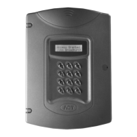
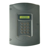
ACTpro 4000 Controller 400mA
ACTpro 1500 Controller 250mA
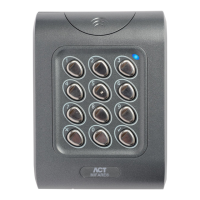
ACTpro 100e Door Station 120mA
ACTpro-X reader (1030/1040/1040/1050/1060) 50mA
ACTPro MIFARE reader (1030/1040/1040/1050) 50mA
Typical Mag Lock (consult your supplier) 800mA