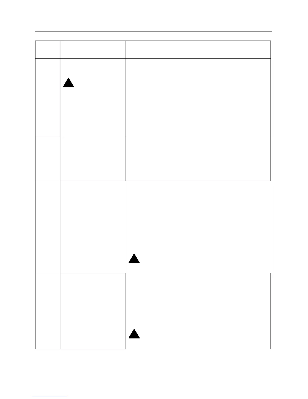
Installing the System Wiring Information and Procedures
Drawing
Ref. No.
Connector Type on ML600
unit
Cabling Requirements
2 ETHERNET 1-4 and
MGMT: RJ-45
!
Caution: Make sure
the RJ-45 plug is properly
crimped. Improper
crimping (protruding pins)
can damage the female
connector.
RJ-45 plug/plug, Category 5, shielded. Connects the ML600
unit to the Ethernet equipment.
3 Craft: DB-9 female, DCE;
DB-9 male connector on one end and DB-9 female connector at
other end. Only wires 2, 3, and 5 are used and connected point-
to-point; connection of the nine pins pin-to-pin is allowed. You
can also use DB-9 female to DB-9 female cable with a male-to-
male adapter. Local management interface connects the ML600
to a Craft terminal, such as a laptop computer, over RS-232.
4
Copper Loops: RJ-45
Connects the ML600 unit to the MDF (using RJ-45 to open
wire cable) or PFU-8 (using 8xRJ-45 to DB-25 cable).
For each connector:
Pin Signal
4 Ring
5 Tip
Note: Do not switch between connections. It is recommended
to mark each cable according to its port.
!
For wire-wrap or IDC applications, use solid 26 –24
AWG wires.
5 Aux
(Not in use in R5.00 SW)
RJ-45 plug/plug. Connects the ML600 unit to the PFU-8.
Allows PFU-8 management via ML600.
Pin Signal
3 Tx
5 Gnd
6 Rx
!
Use only Actelis ML600 to PFU-8 cable. See “Appendix
B, Parts List” in the ML600 User Manual for part number.
16 ML600 Release 5.00 Quick Installation Guide