11
REPLACING THE BALLAST
(
CONT.
)
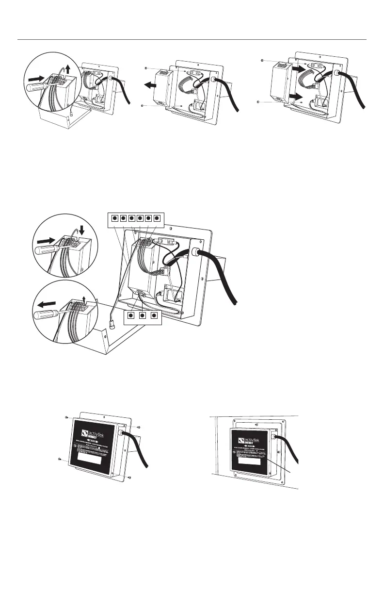
7. Replace cover and secure with the
original four (4) screws.
8. Re-install unit if removed from duct.
Reconnect power and check for proper
operation.
UV Bulb
Indicator
6. To reconnect wiring, (A) press each tab on the ballast and insert wire.
(B) Release tab and gently pull wire to ensure it is properly locked into place.
LED+ LED- RED RED BLUE BLUE
BLACK WHITE GREEN
A
B
UPPER (6 terminals)
• Black LED wire in LED+
• White LED wire in LED-
• 2 Blue wires in BLUE
• 2 Red wires in RED
LOWER (3 terminals)
• Black power wire in BLACK
• White power wire in WHITE
• GREEN is not used
NOTE: UV Bulb Indicator should be lit when
in operation.
4. Remove the two (2) nuts
securing ballast to the case.
Remove the ballast.
5. Place new ballast into the
original location and secure
using the two nuts removed in
step 4.
3. Disconnect all ballast wiring by
pressing down on connector
tabs and pulling wire straight
out.
 Loading...