1 2 3
4
5
6
7
8
9
11
10
12
Horizontal installation Vertical installation
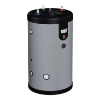
Cold water
Hot water
CONNECTION
Essential instructions forthe safety of persons and the environment
• Refer to the safety instructions for the installation. Failure to comply with these
instructions can result in damages to the system, severe injuries or death.
• Hot water can burn! ACV recommends using a pre- set thermostatic mixing
valve in order to provide hot water at a maximum of 60°C.
Essential instructions forthecorrect operation ofthesystem
• The filling circuit of the DHW tank must be equipped with a safety group,
comprised at least of a stop valve, a check valve, a safety valve set at 7 bar, and
possibly, an expansion vessel of the appropriate size. Make sure that the circuit
between the tank and the safety valve is always open.
• The third DHW tank connection, if any, can be used for the auxiliary DHW loop.
If the connection is not used, replace the protective plug by a brass plug of the
appropriate size.
General remarks
• In certain countries the domestic kits must be approved.
• The circuit illustrations are basic principle diagrams only.
CONNECTION TO THE DHW CIRCUIT (Typical wall installation)
Key
1. Filling valve
2. Pressure reducing valve (set at 4.5 bar)
3. Check valve
4. Stop valve
5. DHW expansion vessel
6. Pressure gauge
7. Safety valve (set at 7 bar)
8. Drain valve
9. Grounding
10. Stop valve
11. Thermostatic mixing valve
12. Hot water outlet
SLE - SLE Plus: A1007847 - 661Y2100 • D
Installation
• To protect the primary circuit when the stop valves are closed, a safety
valve and expansion vessel are imperative between the tank and the
stop vales.