© ADB bvba All Rights Reserved 11
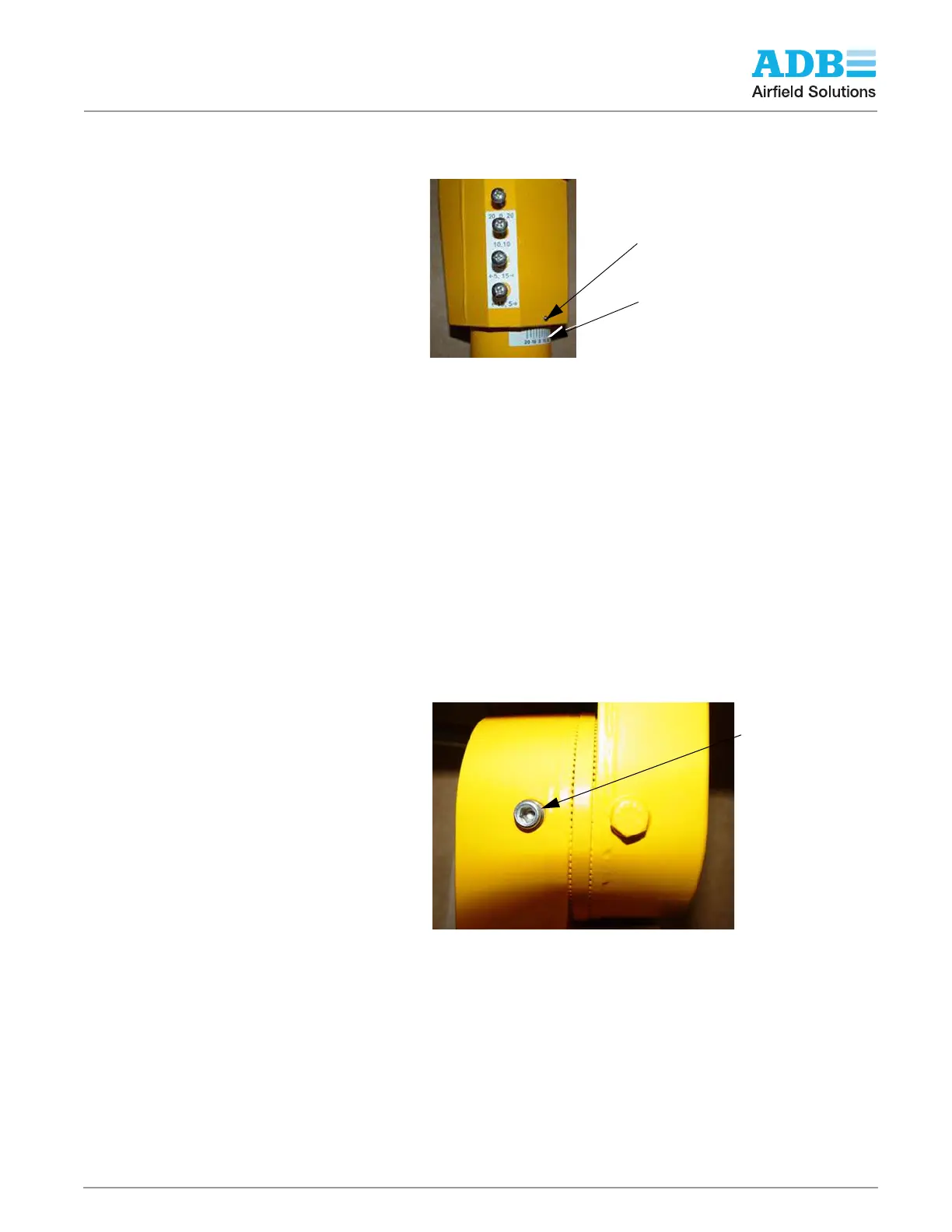
3. Rotate RGL assembly until the indicator pin that is found at the bottom edge of the
adjustable arm hub is aligned with the desired angle. The horizontal angle label that is
affixed to the coupling is marked in 5 degree increments. See the following figure.
NOTE: The appropriate screw to tighten all the way into the mating hole in the frangible
coupling is determined by the degrees adjusted. For example, if the horizontal is adjusted to
20 degrees, the top screw marked 20, 0, 20 should go in all the way. Hand tighten all four
screws. See photos above.
Verify that the selected angle meets the requirements of the site plans and specifications.
If the horizontal aiming angle is not correct make one or both of the following
adjustments:
1. Remove the two screws in the side of the baseplate hub and rotate the coupling slot to
line up with the other tapped hole in the hub. Repeat horizontal aiming procedure above.
2. If additional adjustment is needed then remove the two mounting bolts used to fasten the
baseplate to the L868B light base. Rotate the baseplate either clock or counter-clock
wise at least 30 degrees. Repeat the horizontal aiming procedure above.
3. Once horizontal aiming is completed install and torque all mounting hardware that
secures the baseplate to the L867B light base.
2.3.5.3 Vertical Aiming To adjust the vertical setting, perform the following procedure:
1. See Figure 3. Loosen two Allen hex set screws on side shown in photo and on opposite
side.
2. Loosen hex bolt (6) on the face (side) of RGL.
3. Adjust the vertical setting to the desired number of degrees in one-degree increments by
lining up the indicator pin (9) from 0 to +20 degrees.
4. Tighten the hex bolt (6). Refer to Table 8.
5. Tighten the hex bolts (1). Refer to Table 8.
NOTE: See Figure 3 for additional installation instructions and bolt torque values. Refer
to Table 8.
6. After the RGL has been aimed and operation has been verified, install the tether by
attaching one end of the tether to one of the bolts on the center housing of the RGL and
attach the other end to nearest bolts securing the baseplate to the light base housing. 5..
NOTE: There are two set screws in the side of the hub. These set screws are used when
the RGL is being aimed horizontally.
Horizontal Angle
Label
Indicator Pin
Set Screw - 2 Places
180 Degrees Apart