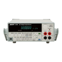
6247G/6247C DC Voltage Current Source/Monitor Operation Manual
Table of Contents
C-2
2.2.3.2 Menu Structure and Parameter Setting ....................................................... 2-28
2.2.4 Initializing Setting Conditions .................................................................... 2-34
2.2.5 DC Measurement ........................................................................................ 2-35
2.2.6 Pulse Measurement ..................................................................................... 2-39
2.2.7 Sweep Measurement ................................................................................... 2-43
2.3 Saving and Loading Parameters ........................................................................ 2-48
2.3.1 Auto Load at Power ON ............................................................................. 2-48
2.3.2 Saving Parameters ...................................................................................... 2-49
2.3.3 Loading Parameters .................................................................................... 2-50
2.3.4 Default Parameters ..................................................................................... 2-51
3. MEASUREMENT EXAMPLE ................................................................ 3-1
3.1 Diode Measurement .......................................................................................... 3-1
3.2 Battery Charge and Discharge Test ................................................................... 3-3
4. REFERENCE ................................................................................................ 4-1
4.1 Menu Index ....................................................................................................... 4-1
4.2 Function Description ......................................................................................... 4-3
4.2.1 AUTO Key (Measurement Range) ............................................................. 4-3
4.2.2 DOWN Key (Source Range) ...................................................................... 4-3
4.2.3 FIT Key (Source Range) ............................................................................ 4-3
4.2.4 HOLD Key (Trigger Mode) ....................................................................... 4-4
4.2.5 LIMIT Key (Limiter Setting) ..................................................................... 4-4
4.2.6 MENU Key (Parameter Setting) ................................................................ 4-4
4.2.7 MODE Key (Source Mode) ........................................................................ 4-16
4.2.8 MON Key (Measurement Mode) ............................................................... 4-16
4.2.9 NULL/SEL Key .......................................................................................... 4-16
4.2.10 OPR/SUSPEND Key (Operating/Suspend) ............................................... 4-17
4.2.11 SHIFT/LOCAL Key (Shift Mode/Local) ................................................... 4-17
4.2.12 STBY Key (Output Standby) ..................................................................... 4-18
4.2.13 TRIG/SWP STOP Key (Trigger/Sweep Stop) ........................................... 4-18
4.2.14 UP Key (Source Range) ............................................................................. 4-18
4.2.15 VS/IS Key (Source Function) ..................................................................... 4-19
4.2.16 123... Key (Direct Input Mode) .................................................................. 4-19
4.2.17 4W/2W Key (Remote Sensingn) ................................................................ 4-19
5. TECHNICAL REFERENCES ................................................................. 5-1
5.1 DUT Connection ............................................................................................... 5-1
5.1.1 Note for Output Terminals ......................................................................... 5-1
5.1.2 Remote Sensing (2-Wire/4-Wire Connection) ........................................... 5-2
5.1.3 Preventing Oscillation ................................................................................ 5-4
5.1.3.1 Preventing 6247G/6247C Oscillation ......................................................... 5-4
5.1.3.2 Preventing DUT Oscillation ....................................................................... 5-5
5.1.4 Connection for High Current Measurement ............................................... 5-6
5.1.5 Connection with Fixture 12701A ............................................................... 5-7
5.2 Functions in Detail ............................................................................................ 5-8
5.2.1 Operations in DC Source Mode ................................................................. 5-8
5.2.2 Operations in Pulse Source Mode .............................................................. 5-10


 To Next Page