Do you have a question about the Adcom GFA-7400 and is the answer not in the manual?
Crucial warnings about electric shock risks and the prohibition of opening the unit.
Guidelines for safe placement of outdoor antennas away from power lines for shock prevention.
Detailed instructions for grounding outdoor antennas to protect against voltage surges and static.
Specific instructions for CATV installers regarding proper building grounding per NEC.
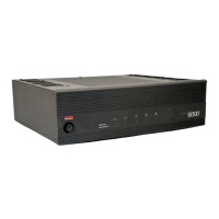
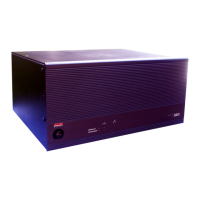
Congratulatory message and introduction to the ADCOM GFA-7400/7300 amplifiers.
Details on the ADCOM Limited Warranty and requirements for proof of purchase.
Key features and technical highlights of the ADCOM GFA-7400 5-channel power amplifier.
Key features and technical highlights of the ADCOM GFA-7300 5-channel power amplifier.
Instructions for unpacking the amplifier and inspecting it for any shipping-related damage.
Guidelines for positioning the amplifier to ensure proper airflow and prevent overheating.
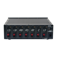
Visual diagram showing how to connect speakers and surround processors to the amplifier.
Explanation of the Left/Right and Front/Rear channel naming conventions for connections.
Detailed guide for using RCA cables to connect audio sources to the amplifier's inputs.
Instructions for connecting speakers to binding posts, including polarity and cable types.
Information on driving low-impedance speakers and using speaker selectors for system expansion.
Proper methods for cleaning the amplifier's chassis and front panel to maintain its finish.
Diagram and description of all connectors found on the rear panel of the amplifier.
Details on RCA inputs and gold-plated binding post outputs, including connector compatibility.
Explanation of the 12VDC trigger feature for remote power control on the GFA-7400.
Information on AC fuse types, ratings, and safe replacement procedures with warnings.
Step-by-step instructions for safely replacing fuses in both the GFA-7400 and GFA-7300 models.
Guidelines for using the polarized AC power cord to ensure safety and minimize hum.
How to operate the power switch to turn the amplifier on and off correctly.
Explanation of the Power LED's function, including its behavior during operation and shutdown.
Details on the thermal protection circuit, its triggers, and how it affects amplifier operation.
Meaning of the Distortion Alert LEDs and guidance on reducing volume to prevent damage.
A table listing common symptoms, potential causes, and solutions for amplifier problems.
Explanation of common audio hum issues and the concept of ground loops.
Steps to identify and resolve hum issues related to Cable TV connections using isolators.
Troubleshooting hum by adjusting component spacing and testing RCA cables individually.
Information on how to contact ADCOM's Technical Service Department for assistance and advice.
Guidelines for shipping the amplifier for service, including packaging and prior authorization requirements.
Detailed specs for power output, IM distortion, THD+Noise, and frequency response.
Specs on headroom, S/N ratio, gain, input sensitivity, impedance, damping factor, and rise time.
Specifications for chassis dimensions, maximum dimensions, weight, and power consumption.
Detailed specs for power output, IM distortion, and THD+Noise for the GFA-7300.
Specs on headroom, S/N ratio, gain, input sensitivity, impedance, damping factor, and rise time.
Specifications for chassis dimensions, maximum dimensions, weight, and power consumption.
The ADCOM GFA-7400 and GFA-7300 are high-current, 5-channel power amplifiers designed for high performance and musical accuracy, specifically configured to integrate with home theater processors. These amplifiers are engineered to provide exceptional sound reproduction for years to come.
The GFA-7400 and GFA-7300 serve as the core of a home theater audio system, amplifying audio signals from a preamplifier or surround sound decoder to drive loudspeakers. They are designed to handle a wide range of audio demands, from subtle nuances to high-volume playback, ensuring a dynamic and accurate sound experience. The amplifiers feature precision-matched devices throughout the signal path, contributing to their high fidelity. Each channel benefits from independent power supplies and large power supply-filter capacitance, providing significant reserve capacity for demanding audio passages. Custom toroidal power transformers ensure better regulation and greater peak current capability. The design incorporates fewer gain stages to improve signal reproduction accuracy.
The amplifiers are equipped with several features to enhance usability and protect the unit. Each of the five channels has independent thermal-overload and distortion LEDs. The "distortion alert" circuit is a unique ADCOM system that detects all forms of non-linear distortion, such as THD, IM, slew-induced distortion, and clipping. These LEDs illuminate when distortion reaches approximately 1%, regardless of impedance or loudspeaker reactance, serving as a warning that the amplifier is approaching its maximum power output. Occasional flickering during high-volume listening is normal, but bright or constant illumination indicates overdriving, suggesting a need to reduce volume or correct load impedance.
The "thermal protection" LEDs light up when the heatsink temperature reaches 85°C, indicating that the thermal protection circuit has been triggered and the respective amplifier channel is inoperative. This typically occurs under very high power demands into low impedances. The amplifier will automatically resume operation once the heatsink temperature drops to a safe level. Consistent activation of thermal protection suggests the amplifier is being overdriven or the loudspeakers present an unreasonably low load, requiring adjustment of volume or load impedance.
Input connections are made via high-quality, gold-plated RCA jacks, designed to minimize high-frequency losses and noise. These accept standard RCA-type plugs for the Front Left, Center, Right Front, Left Rear, and Right Rear channels. For optimal performance, high-quality, low-loss, low-capacitance audio cables are recommended.
Output connections to loudspeakers are made through high-grade, gold-plated binding post terminals. There are two terminals for each speaker: RED for positive (+) and BLACK for negative (-). The GFA-7400 features 5-way binding posts, while the GFA-7300 has similar high-grade, gold-plated binding posts that easily accept stripped bare wires or pins. For spade lugs on the GFA-7300, a black molded plastic guide block needs to be removed. The binding posts accommodate various connector types, with "U"-type spade connectors being the most secure. Proper polarity (positive to positive, negative to negative) is crucial for speaker connections. The amplifiers are "polarity correct," meaning they do not invert phase from input to output.
A convenient 12 VDC power ON/OFF triggering feature is available on the GFA-7400, allowing it to be controlled by certain ADCOM pre-amplifiers and tuner pre-amplifiers. The front panel Power Switch must be left in the "on" position for this feature to work. A monaural mini phone plug cable (not included) is required for connection. The trigger circuit operates from approximately 5 to 30VDC, with the center conductor (tip) being positive.
The front panel includes an On/Off Switch that controls power to the transformer and circuits. When energized, the Power LED glows. The Power LED indicates AC voltage is supplied but does not confirm all amplifier circuits are operational. If a Thermal Protection LED glows, that channel will not produce sound even if the Power LED is on. The Power LED fades out slowly after shutdown. An internal thermostat protects the transformer from overheating, interrupting power if the temperature exceeds 125°C. This rarely occurs under normal conditions and typically resets automatically once the temperature decreases.
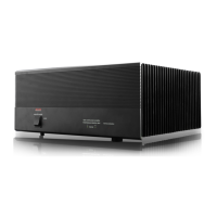
The GFA-7400 and GFA-7300 are built with heavy-gauge, anodized aluminum front panels and powder-coated, baked steel chassis and top covers for durability. Cooling vents on the top and bottom panels ensure efficient cooling, especially when driving low impedance loads. It is crucial to keep these vents unobstructed and to avoid placing the amplifier near external heat sources or in enclosed cabinets without free airflow. Stacking other components on top is not recommended, particularly with low-impedance loudspeakers or high-volume usage, as this can impede airflow and affect performance. Regular cleaning of accumulated dust on the chassis, panels, and around vents with a soft, lint-free cloth, slightly dampened with a mild detergent solution or glass cleaner, is recommended. Liquids should never be sprayed or poured directly onto the unit.
The AC fuse protects the electronic circuits from overload. In case of a blown fuse, it must be replaced with an identical type and rating as printed on the rear panel. For the GFA-7400, a 1/8-turn counter-clockwise turn with a standard flat-blade screwdriver removes the fuse-holder cap. For the GFA-7300, a #2 Philips type screwdriver is needed, and the cap is turned counter-clockwise. Always unplug the AC power cord before replacing a fuse to prevent electrical shock. Using incorrect fuses can cause serious damage, fire hazards, and void the warranty. If the Power LED does not glow, it may indicate a blown AC fuse or a problem with the 12VDC Triggering feature (GFA-7400 only). Disconnecting the trigger plug and manually cycling the power switch can help diagnose issues with the trigger circuit.
For speaker cables, it is vital to use the correct gauge to avoid power loss, reduced damping factor, and other undesirable conditions. AWG16 stranded copper cable is suggested as a minimum, with recommendations for AWG14 and AWG12 for longer runs. The recommended capacitance of speaker wire should not exceed 50pF per foot to ensure high frequencies are not rolled off.
Troubleshooting guidance is provided for common issues like no power, no sound, sound from only one channel, or hum. Ground loops, often caused by differences in ground voltages between components or by cable TV systems, are a common source of hum. Disconnecting the cable TV incoming signal line can help identify if it's the cause, in which case a "75Ω Ground Loop Isolator" may be needed. Ensuring the power amplifier is at least 6 inches away from the preamplifier/processor can also help minimize hum. If issues persist, consulting an ADCOM dealer or service center is advised.
| continuous power per channel into 8 ohms | 100 watts |
|---|---|
| continuous power per channel into 4 ohms | 150 watts |
| power consumption quiescent | 96 VA |
| maximum power consumption | 1440 VA |
| power consumption at 100 watts into 8 ohms | 1165 VA |
| power supply voltage | 115 VAC - 50/60 Hz |
| IM distortion SMPTE at 8 ohms | ≤ 0.075% |
|---|---|
| IM distortion SMPTE at 4 ohms | ≤ 0.075% |
| IM distortion CCIF at 8 ohms | ≤ 0.025% |
| IM distortion CCIF at 4 ohms | ≤ 0.025% |
| THD + noise at 100 watts into 8 ohms at 20Hz | 0.0012% |
| THD + noise at 100 watts into 8 ohms at 1kHz | 0.0012% |
| THD + noise at 100 watts into 8 ohms at 10kHz | 0.02% |
| THD + noise at 100 watts into 8 ohms at 20kHz | 0.025% |
| THD + noise at 150 watts into 4 ohms at 20Hz | 0.025% |
| THD + noise at 150 watts into 4 ohms at 1kHz | 0.025% |
| THD + noise at 150 watts into 4 ohms at 10kHz | 0.035% |
| THD + noise at 150 watts into 4 ohms at 20kHz | 0.045% |
| frequency response at 1 watt into 8 ohms | +0, -0.25 dB |
|---|---|
| power bandwidth | 1.5 Hz to 65 kHz |
| dynamic headroom into 4 ohms | 2.5 dB |
| signal to noise ratio | ≥ 110 dB |
| gain | 29 dB |
| input sensitivity for 1 watt | 0.1 volts |
| input sensitivity for 100 watts | 1.0 volts |
| input impedance | 50 kΩ |
| damping factor | ≥ 400 |
| rise time | 4.5 µS |
| chassis dimensions | 5” (127mm) x 17” (432mm) x 14” (355.6mm) |
|---|---|
| maximum dimensions | 5 3/4” (146mm) x 17” (432mm) x 15” (381mm) |
| weight | 42 lb. (19.1 kg) |
| packed weight | 48 lb. (22.8 kg) |