The IRIS-4 50 is a terminal designed for alarm transmission, offering quick installation and maintenance. It supports various transmission paths, including cellular and IP, and provides multiple interfaces for connecting to alarm panels and monitoring centers.
Function Description
The IRIS-4 50 serves as a communication device for alarm systems, enabling the transmission of alarm signals to a monitoring center. It supports both cellular (2G, 3G, 4G) and IP-based communication. The terminal can interface with alarm panels via dial capture (PSTN emulation), pin inputs, serial interface (RS232), and relay outputs. It is designed to be mounted within an existing tamper-protected alarm panel enclosure.
Important Technical Specifications
Transmission Paths:
- Cellular:
- LTE (4G) Cat1: B28A(700MHz), B20(800MHz), B8(900MHz), B3(1800 MHz), B1(2100MHz), B7(2600MHz)
- UMTS (3G): B8(900MHz), B3(1800MHz), B1(2100 MHz)
- GPRS (2G): B8(900MHz), B3(1800MHz)
- Connection: SMA socket for antenna
- Fault detection: Loss of registration with network, loss of connectivity to ISA/ARC
- IP:
- TCP ports (outbound): 53165 (Alarms and Polling), 51292 (Diagnostic and Reflashing), 10001 (Upload/Download)
Alarm Transmission:
- Interface to Monitoring Center: ISA or IRIS Management Suite via EN 50136-2 pass-through mode
- Dial capture interface to alarm panel: Two-wire interface (cabling must not exceed 3 meters)
- Serial interface to alarm panel: RS232 (basic TX/RX) (cabling must not exceed 3 meters)
- PIN Inputs interface:
- Maximum input voltage range: 0V to +28V DC
- Input 'low' (alarm) threshold: < 1V
- Input 'high' (restore) threshold: > 2V
- Selectable internal pull-up impedance: 10K to 3.3V supply (cabling must not exceed 3 meters)
Power Supply:
- Supply voltage: 5-28 VDC
- Typical current: 80mA @ 12VDC, 40mA @ 24VDC
- Maximum current: 1A @ 12VDC
- Recommended external PSU: 12V DC 1A 12 Watt (cabling must not exceed 3 meters)
Environmental:
- Operating temperature range: -10°C to 55°C
- Operating humidity range: 95% max., non-condensing
- Environmental Class II
Physical Dimensions:
- Physical dimensions: 87mm x 55mm x 16mm
- Terminal weight: 85 grams (with wire harness)
- Fully packaged weight: 200 grams
Alarm Protocols:
- SIA (level 1 to 3) reference SIA DC-03-1990.01(R2003.10)
- Contact ID reference SIA DC-05-1999.09
- FF (Scancom)
- Robofon (dial capture only)
- Telim (dial capture only)
- CESA (dial capture only)
- Dial capture interface
- Serial Interface
- Pin inputs
- Transmission interface/path fault
Compliance:
- EN50131, EN50136
- EN 50131-10:2014 Type Y
- EN 50136-1:2012 SP5
- EN 50136-2: 2013 SP5
- Security Grade 4 when mounted in a Grade 4 Alarm Transmission System (ATS)
- SELV compliant
- European Directives: 2014/53/EU (Radio Equipment Directive), 2012/19/EU (WEEE2), 2015/863/EC (ROHS 3), No. 1907/2006 (REACH)
Usage Features
Package Contents:
The package includes the terminal, a cable harness loom, a cellular T-bar antenna (2.5m long), Velcro mounting pads, an adhesive mounting pad, and a cable tie wrap for mounting.
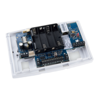
Terminal Layout:
The terminal features a signal strength/default button, a USB micro connector, and a cable harness loom with color-coded identification. It has a cellular antenna connection, a Terminal Activation Code (TAC), and LED indicators for panel interface status (red), cellular status (yellow), and terminal status (green).
Installation:
- Cable harness attachment: Connect the cable harness to the terminal, aligning the connector and matching wire colors to the label.
- Mounting: Mount the terminal within an existing tamper-protected alarm panel enclosure using Velcro pads, adhesive mounting pad, or cable ties. Ensure interface cables can reach their destinations and consider cellular antenna placement.
- Connecting cellular: Connect the antenna to the terminal and position it away from metal surfaces or obstructions for good signal strength. Do not fix the antenna until signal strength is checked after power-up.
- Connecting to the alarm panel:
- Dial capture: Connect to the alarm panel's PSTN dialer interface (polarity is not important).
- Pin inputs: Connect to appropriate outputs from the panel. By default, these inputs are disabled and should be configured as open circuit in alarm condition.
- Relay Outputs: Connect Relay A and/or B to alarm panel inputs if signaling back is required. Relay contacts are voltage-free. By default, Relay A signals 'General Fault'.
- Serial: Connect RX and TX to the panel's serial interface. Default is 9600bps using IRIS API protocol.
Connecting Power:
The terminal is powered via the cable connection to the DC supply from the alarm panel. Power is provided, the terminal will:
- Instigate connection to the cellular network, using the eSIM already fitted.
- Report status on the LEDs, as described in the LED Indications table.
LED Indications:
- Terminal status (green):
- On, steady: No faults.
- Flashing, on 0.5s, off 0.5s: One or more fault present.
- Cellular (yellow):
- On: Cellular OK, will flicker off for 0.1s to show polling to alarm receiver at ARC.
- Flashing, 0.5s on, 0.5s off: Polling failed or not configured.
- Flashing, 0.1s on, 0.9s off: Registered to cellular network, but no IP connection.
- Panel (red):
- Off: Not registered to cellular network.
- On: Panel interface OK.
- Flashing, on 0.5s, off 0.5s: Panel interface fault, either Dial Capture tamper, pin input tamper or no serial activity. Note each of these fault notifications are disabled by default.
- All LEDs: Will flash together for a short period when the terminal has been defaulted. Will blink together for a short period if the terminal is installing new software.
Configuring the Terminal:
The terminal can be configured using the IRIS Toolbox software application on a PC connected to the terminal with a USB cable. Toolbox software version 4.7.1 or later is required.
To reset to factory default settings:
- Power down the terminal.
- Hold down the default/signal strength button.
- Power up the terminal.
- Continue to hold the button down for 5s and then release it.
The LEDs will flash to indicate the default has occurred, as described in the LED Indications table.
Commissioning Test:
Once configuration is complete, perform a full commissioning test in collaboration with the ARC. This involves normally involving testing normal alarm transmissions from the alarm panel to the ARC and verifying acknowledgement of these alarms with the operators at the ARC.
Maintenance Features
Maintenance:
Inspect the terminal on an annual basis. At each inspection, perform the following routine:
- Check the terminal mountings are still secure.
- Confirm the current status of the terminal from the LEDs.
- Clear any faults on the terminal.
- Check if the terminal is running the latest software.
- Perform full test of alarms from the alarm panel and confirm acknowledgement of these by the operators at the ARC.
You can check for current faults, reflash to the latest software, perform communication path checks and other tasks using the IRIS Toolbox.