PowerLab Teaching Series - Owner’s Guide
31
The External Trigger
The external trigger input (not on PowerLab 15T) is marked ‘Trigger’ on the front panel
and provides a digital input for synchronizing sampling with external devices. It allows
either a voltage level or a contact closure to trigger recording. Note that for either mode
the trigger signal must be present for at least 3 μs to register as an event. When a trigger
event occurs, the indicator light will glow yellow.
When set up through so ware to use a voltage level, above which a rising edge trigger
event is registered, the external trigger level is 2 V. The external trigger input is o for
input voltages between –12 V and the external trigger level, and on between that level
and +12 V. The input will be overloaded if the voltage is outside the range –12 V to +12 V.
The trigger input is isolated whenset up for a voltage level.
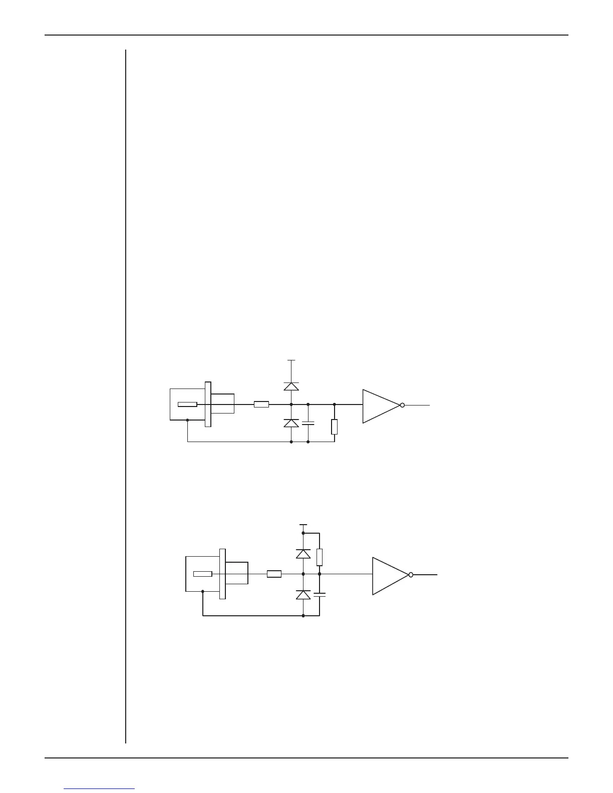
The equivalent circuit of the external trigger has two diode protection.In the external
contact closure mode, the trigger input will respond to a direct short between the center
pin and outer ring of the BNC. This can be achieved with an external relay contact, a
manual push-button or a microswitch. The trigger input is not electrically isolated when
set up for contact closure.
The equivalent circuit for the external closure trigger is shown in Figure A–3. The BNC
input connects to a TTL circuit via a resistor circuit and has two-diode protection.
In order for the external trigger to work, a voltage must be applied between the outer
ring and the inner pin of the connector. Applying a voltage just to the center pin may not
work.
1.2Kohm
Resistor
47Kohm
Resistor
+3.3V
100pF
Trigger
(BNC connector)
1.2Kohm
Resistor
47Kohm
Resistor
+3.3V
100pF
Trigger
(BNC connector)
Figure 4-4
The equivalent circuit
of the external trigger
input, when set up for
contact closure
Figure 4-3
The equivalent circuit
of the external trigger
input, when set up for
a voltage level