PowerLab Teaching Series - Owner’s Guide
35
I
2
C Expansion Connector
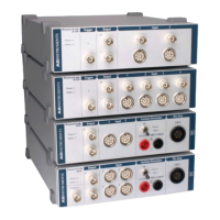
The I2C port on the back panel of the PowerLab 2/26, 4/26 and 26T provides expansion
support for ADInstruments front-ends. This port provides both power and control
signals for these front-ends. The I2C bus has a daisy-chain structure that allows simple
connection of additional front-ends to the system. A PowerLab can have as many front-
ends connected to it as it has analog input connections. You should not attempt to run
other external devices from the I2C port: it is designed for use only with ADInstruments
front-ends. Only 50 mA maximum current can be provided through this bus, so it should
not be used for third-party devices as they may draw more current.
IN 1
GROUND
5 V
18
159
IN 2
IN 3
IN 4
IN 5
IN 6
IN 7
IN 8
Digital Input
OUT 1
GROUND
5 V
81
915
OUT 2
OUT 3
OUT 4
OUT 5
OUT 6
OUT 7
OUT 8
Digital Output
1
6
DGND
UNREG-15V
5
9
UNREG+7V
UNREG+15V
SCL
DSC
SDA
DSD
IN T
Front-end power IC control signals
Figure 4-8
The pin assignments
for the I
2
C connector
Figure 4-7
The pin assignments
for the digital input
and output
connectors