PowerLab Teaching Series - Owner’s Guide
32
Bio Amp Input (Inputs 3 & 4)
The PowerLab 15T and 26T have one common connector for two Bio Amp channels,
marked Bio Amp 3 & 4. These two independently controllable, electrically isolated,
biological amplifiers are suitable for a range of basic physiological measurements. The
two Bio Amp inputs are internally configured to use channels 3 and 4 of the PowerLab.
The Bio Amps have a common six-pin connector with a shared ground.
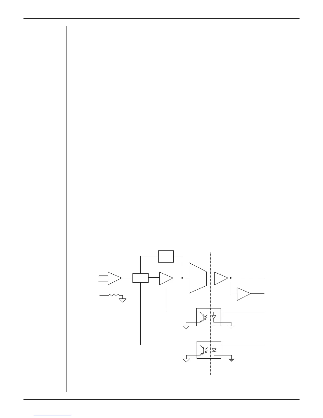
Each amplifier consists of an electrically isolated, AC coupled, di erential amplifier with
programmable gain able to be set independently (the gain is set through the so ware
range control: the less the range, the more the gain). The gain is controlled by optically
isolated digital control signals from the nonisolated section. The signal is then applied
to an isolation amplifier which provides electrical isolation of the input stage from the
supply.
The non-isolated stage consists of a series of filters and amplifiers. The first part of the
stage is a high-pass filter designed to remove any DC components from the signal and
the isolated stage. This is followed by amplification and an active notch filter. The notch
can be turned on or o under so ware control as needed. The frequency of the notch
filter is automatically set to either 50 or 60 Hz to match the frequency of the connected
power supply.
The low-pass filter is an eighth-order, switched-capacitance, Bessel-type filter, with
a so ware-selectable range of frequencies. The output of the biological amplifier is
then passed to the standard PowerLab input amplifier circuit. On the PowerLab 26T an
amplifier connected to the output of the biological amplifier is used to provide an audio
output facility that can be used with headphones or powered speakers.
HPF
IGND
IGND
GND
GND
Output
Audio output(26T)
Isolation amplifier
Auto
restore
Gain control
HPF control
Isolation barrier
+
-
Signal
Input
Reference
IGND
Figure 4-5
Block diagram for one
of the two
Bio Amplifiers
(Input 3 & 4)