ADJ Products, LLC - www.adj.com - UV LED Bar20 Instruction Manual Page 7
The display will lock after 30 seconds, press the MODE
button for 3 seconds to unlock.
LED Display On/Off: To make the display stay ON all of the time
press the MODE until “ds-X” is displayed. Press the UP button so
that “ds-1” is displayed. The LED display will stay ON all of the time.
To make the display turn OFF after 10 seconds, press the UP button
so that “ds-2” is displayed. When the LED display turns OFF after 10
seconds, press any button for at least 3 seconds to turn the display
on again.
DMX Mode:
Operating through a DMX controller give the user the freedom to cre-
ate their own programs tailored to their own individual needs. The UV
LED Bar20 has 3 DMX modes: 1 Channel Mode, 2 Channel Mode,
and 3 Channel Mode.
1. This function will allow you to control each individual fixture’s
traits with a Elation® DMX 512.
2. Use the MODE button to scroll through the DMX Channel modes.
The Channel modes are listed below:
• To run the 1 Channel Mode, press the MODE button until “1XXX”
is displayed. “XXX” is the current displayed DMX address. Use
the UP or DOWN buttons to find your desired DMX address.
• To run the 2 Channel Mode, press the MODE button until “2XXX”
is displayed. “XXX” is the current displayed DMX address. Use
the UP or DOWN buttons to find your desired DMX address.
• To run the 3 Channel Mode, press the MODE button until “3XXX”
is displayed. “XXX” is the current displayed DMX address. Use
the UP or DOWN buttons to find your desired DMX address.
3. Once you have found your desired DMX Channel mode and
address, plug in the fixture via the XLR connections to any stan-
dard DMX controller.
4. Please see pagess 10 -11 for DMX values and traits.
Static Mode:
In this mode the UV light will remain static. You can adjust the inten-
sity in this mode as well.
1. Plug the fixture in and press the MODE button until “4XXX” is dis-
played.
UV LED Bar20 Operating Instructions
ADJ Products, LLC - www.adj.com - UV LED Bar20 Instruction Manual Page 6
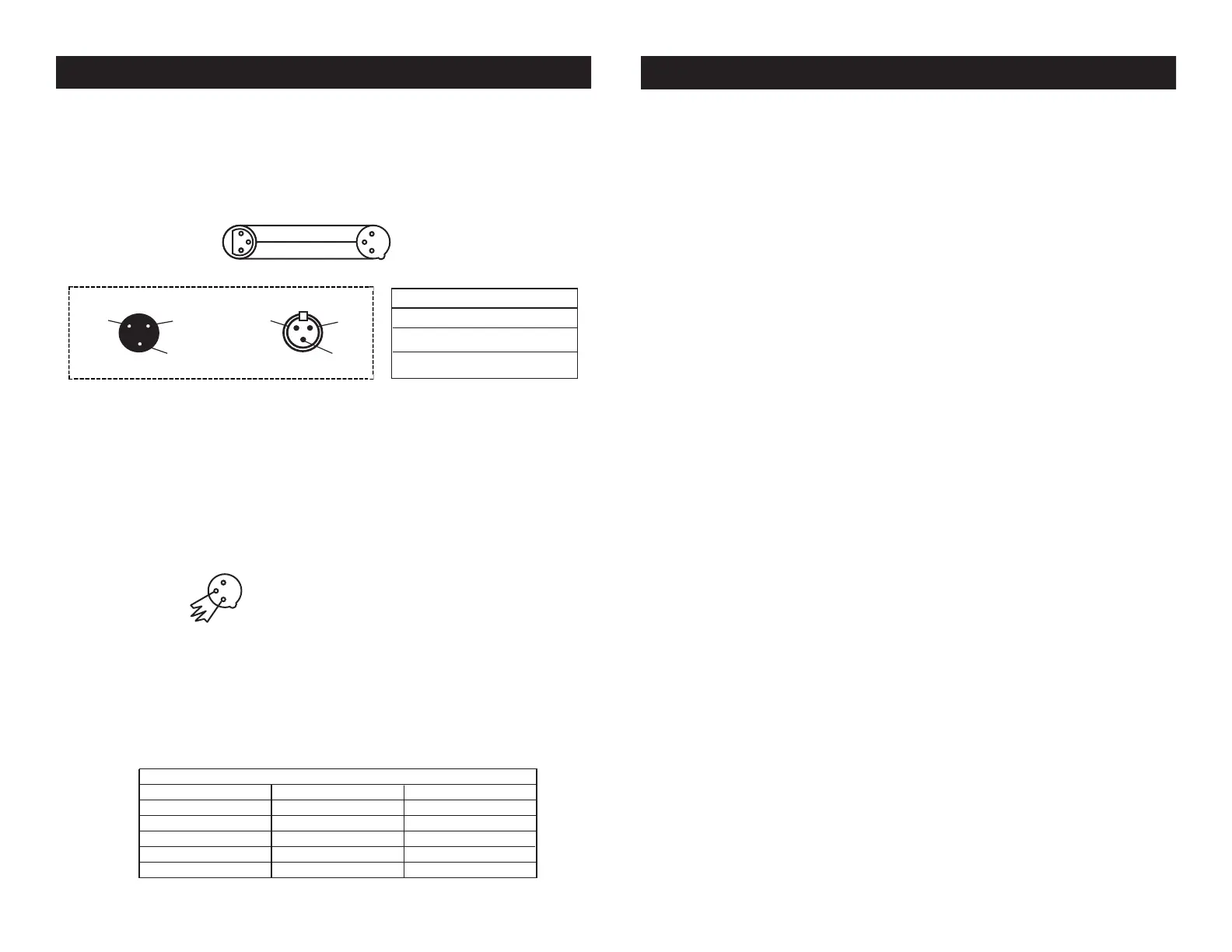
Notice: Be sure to follow gures two and three when making your own
cables. Do not use the ground lug on the XLR connector. Do not con-
nect the cable’s shield conductor to the ground lug or allow the shield
conductor to come in contact with the XLR’s outer casing. Grounding
the shield could cause a short circuit and erratic behavior.
UV LED Bar20 Set Up
DMX512 IN
3-PIN XLR
SOUND
REMOTE
CONTROL
INPUT
POWER
INPUT OUTPUT
SOUND
REMOTE
CONTROL
INPUT
POWER
INPUT OUTPUT
SOUND
REMOTE
CONTROL
INPUT
POWER
INPUT OUTPUT
DMX512
DMX+,DMX-,COMMON
1
2
3
Termination reduces signal errors and
avoids signal transmission problems
and interference. It is always advisable
to connect a DMX terminal, (Resistance
120 Ohm 1/4 W) between PIN 2 (DMX-)
and PIN 3 (DMX +) of the last fixture.
1
2
3
1
2
3
DMX +
DMX -
COMMON
DMX512 OUT
3-PIN XLR
Figure 2
Figure 3
1 Ground
1 Ground
XLR Male Socket
XLR Pin Conguration
3 Hot
2 Cold
2 Cold
3 Hot
XLR Female Socket
Pin 3 = Data True (positive)
Pin 2 = Data Compliment (negative)
Pin 1 = Ground
Special Note: Line Termination.
When longer runs of cable are
used, you may need to use a terminator on the last unit to avoid erratic
behavior. A terminator is a 110-120 ohm 1/4 watt resistor which is con-
nected between pins 2 and 3 of a male XLR connector (DATA + and
DATA -). This unit is inserted in the female XLR connector of the last
unit in your daisy chain to terminate the line. Using a cable terminator
(ADJ part number Z-DMX/T) will decrease the possibilities of erratic
behavior.
DMX512 IN
3-PIN XLR
SOUND
REMOTE
CONTROL
INPUT
POWER
INPUT OUTPUT
SOUND
REMOTE
CONTROL
INPUT
POWER
INPUT OUTPUT
SOUND
REMOTE
CONTROL
INPUT
POWER
INPUT OUTPUT
DMX512
DMX+,DMX-,COMMON
1
2
3
Termination reduces signal errors and
avoids signal transmission problems
and interference. It is always advisable
to connect a DMX terminal, (Resistance
120 Ohm 1/4 W) between PIN 2 (DMX-)
and PIN 3 (DMX +) of the last fixture.
1
2
3
1
2
3
DMX +
DMX -
COMMON
DMX512 OUT
3-PIN XLR
Figure 4
5-Pin XLR DMX Connectors.
Some manufactures use 5-pin XLR
connectors for DATA transmission in place of 3-pin. 5-pin XLR xtures
may be implemented in a 3-pin XLR DMX line. When inserting stan-
dard 5-pin XLR connectors in to a 3-pin line a cable adaptor must be
used, these adaptors are readily available at most electric stores. The
chart below details a proper cable conversion.
Conductor 5-Pin XLR Male (In)3-Pin XLR Female (Out)
Pin 1
Do Not Use
Do Not Use
Pin 3
Pin 2
Pin 1
Pin 3
Pin 2
Not Used
Not Used
Data True (+ signal)
Data Compliment (- signal)
Ground/Shield
3-Pin XLR to 5-Pin XLR Conversion


 To Next Page
 Loading...