ADT-CNC46XX 系列维护手册
- 82 -
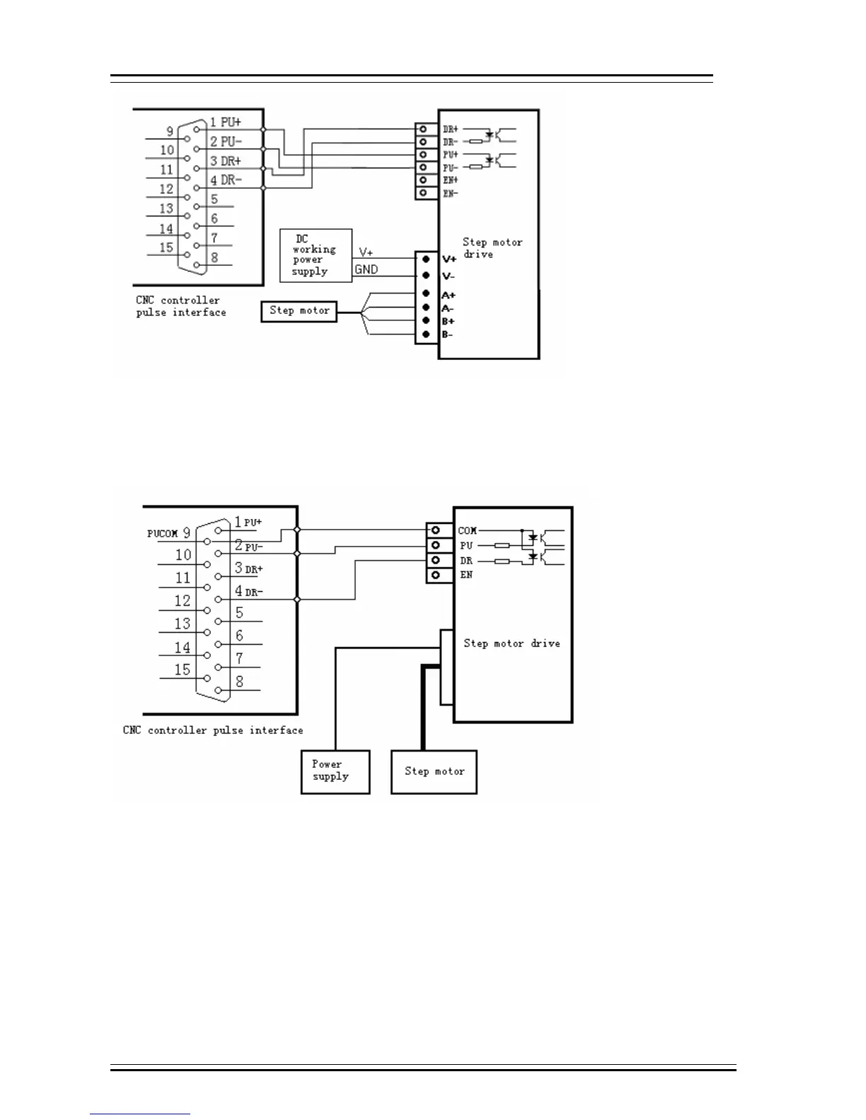
Step motor drive wiring diagram for single-ended input
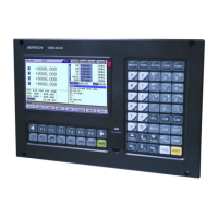
Certain companies connect together the optocoupler input cathodes of step drives, i.e. common cathode
connection, which isn’t suitable for CNC controller. Common anode connection connects together the anodes
of optocoupler input. The wiring shall follow the figure below, and do not connect PU+ and DR+ together, or
else the pulse interface may be damaged.
Wiring Diagram for Step Motor Drive with Common Anode Input
Servo motor drive wiring diagram
Since differential connection is used in most cases, please refer to differential mode for the pulse
connection. Most servo drives require 12-24V power supply, and the 24V power provided by pin 10, 11 is
available. The specific connection depends on servo drive. Please contact us if you have any question.
0 Caution
Either two of PU+, PU-, DR+ and DR- shouldn’t be connected, or else the pulse interface may be damaged.