2 61287835F1-13A
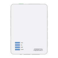
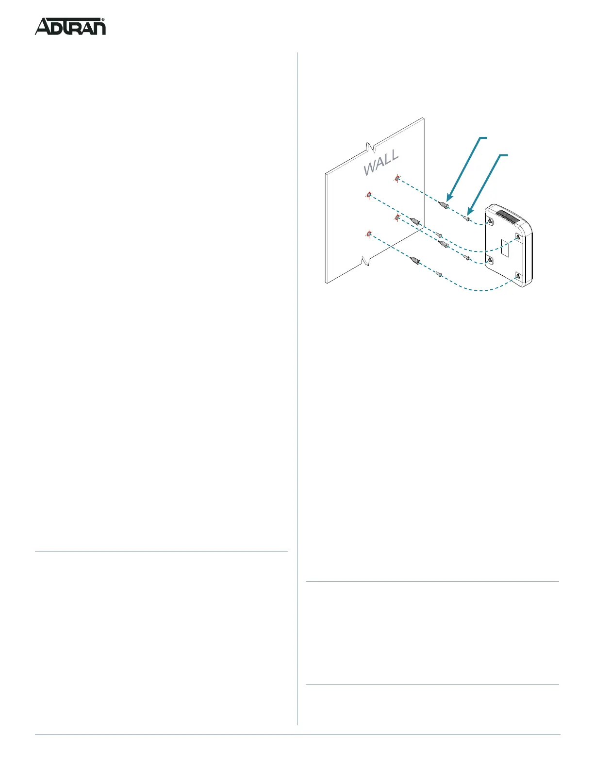
To wall mount the 424 ONT, refer to Figure 1 and complete the
following steps:
1. Decide on a location for the 424 ONT. Mount below eye-
level so the LEDs are visible.
Figure 1. Wall Mount Installation
2. Use the keyholes on the rear of the 424 ONT as a template
and mark the wall accordingly.
3. Use a hammer to lightly tap the included wall anchors into
the marks until the threads are close to the wall. You can
also pre-drill holes using a 1/4” drill bit if difficulty is
encountered.
4. Insert either a #2 or #3 Phillips head screw driver into the
recess of the anchor head.
5. Using gentle forward pressure, rotate the wall anchor
counter-clockwise until the collar is flush with the wall.
6. Install four included screws into the anchor heads. Leave
approximately 1/4 inch (6 mm) protruding from the mounting
surface.
7. Slide the 424 ONT over the screws and exert a small
amount of downward pressure to ensure that the top of the
slots are resting on the shafts of the screws.
Alternately, wall anchors are not needed if mounting directly to
wall studs.
Step 2: Connect Telephone
The 424 ONT has two telephone connections labeled PHONE1
and PHONE2 on the rear of the 424 ONT. To connect the primary
telephone line, simply plug the RJ-45 cable running from the
primary telephone unit into the PHONE1 connection on the rear of
the 424 ONT. Any subsequent phones will be connected to the
PHONE2 jack.
Step 3: Connect Internet
The 424 ONT supports four 1 Gigabit (10/100/1000Base-T)
Internet connections labeled GE1 through GE4. To connect the
primary computer to the Internet, simply plug the Ethernet cable
Installation Guidelines
The following are guidelines for this installation.
■ Read all warnings and cautions before installing or servicing
the 424 ONT.
■ Do not locate the 424 ONT in direct sunlight or next to any
thermal devices.
Installation Overview
To install the 424 ONT, you will need to complete the following
steps:
■ “Step 1: Installing the 424 ONT”
■ “Step 2: Connect Telephone”
■ “Step 3: Connect Internet”
■ “Step 4: Clean Fiber Optics Cable Connections”
■ “Step 5: Connect Fiber Optics Cable”
■ “Step 6: Connect Power”
■ “Step 7: Connect UPS”
Required tools
Standard technician tools and those listed below are required for
installing the 424 ONT:
■ Carpenter’s level
■ Four #8 Pan Head screws (1 inch or greater in length)
■ #2 or #3 Phillips head screw driver
■ Drill
■ Hammer
■ A telephony/data communication test set
■ PON power meter with wavelength filtering
■ Fiberscope or videoscope
■ Assorted tie wraps for securing cabling and wiring
For fiber optic connections, the following are required:
■ Fiber optical fusion splice tools
■ ODC Fiber cleaning tool
■ SC Fiber connector
Step 1: Installing the 424 ONT
Installation consists of either placing the 424 ONT on a flat
surface, for example, a desk, or, mounting the ONT to a wall.
Desktop Placement
The 424 ONT can sit on a desktop or equivalent flat, stable
surface. Do not place the 424 ONT in direct sunlight or next to any
thermal obstructions.
Wall Mount Installation
Refer to Figure 1 when installing the 424 ONT on a wall mount.