EasyManua.ls Logo

Advantech ADAM-6251 User Manual

Advantech ADAM-6251
192 pages
To Next Page IconTo Next Page
To Previous Page IconTo Previous Page
Page #118 background imageLoading...
Page #118 background image
ADAM-6200 User Manual 112
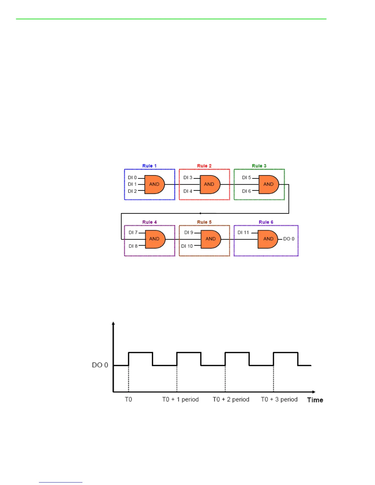
You can simply implement one AND logic operator to achieve this control system.
However, since one logic rule only has three inputs, we need to use Logic Cascade
function to have 12 inputs. There are two ways to achieve Logic Cascade:
a. Select SendtoNextRule in Execution Stage of one logic rule. It will combine this
logic rule to the next logic rule.
b. Assign output of one logic rule and input of another logic rule to the same inter-
nal flag, combining the two logic rules together.
With the first method, the two logic rules must be next to each other. For example,
rule 1 and rule 2 can be combined together. But you cannot combine rule 1 and rule
3. There is no such limitation if you use the second method to combine two different
logic rules. Using the second method, you can even combine two rules on different
modules together. Here, this example project adapts the first method for Logic Cas-
cade. So the GCL logic architecture can be shown as below:
5. Flicker
Flicker is commonly used in automation control application. Typical example is we
want to make the alarm flashing, controlled by digital output. This application requires
a continuous pulse train by a digital output channel and we can decide the period of
the pulse train. The time chart for flicker application can be shown as below:
We need to use 1 Internal Flag (Flag 0) and 2 logic rules for the Flicker application
described above. In logic rule 1, the value of Flag 0 is inverted (By choosing NAND in
the Logic stage) periodically. (Here, it is 0.5 second) The period is defined by the
Execution_Period in the Execution Stage. The status of DO 0 is controlled by Flag 0

Table of Contents

Other manuals for Advantech ADAM-6251

Question and Answer IconNeed help?

Do you have a question about the Advantech ADAM-6251 and is the answer not in the manual?

Advantech ADAM-6251 Specifications

General IconGeneral
ModelADAM-6251
CategoryControl Unit
Digital Input Channels8
Digital Output Channels8
Communication InterfaceEthernet
Power Input10 ~ 30 VDC
Digital Input TypeSink/Source
Input TypeDry Contact
Output TypeSink
ProtocolsModbus TCP
Humidity10 ~ 90% RH (non-condensing)
Input Voltage10 ~ 30 VDC

Summary

Safety Instructions

Chapter 1 Product Overview

1.2 Feature Highlights

Key features of the ADAM-6200 series, including installation and management.

Chapter 2 Product Specifications

2.2 Analog Input Module (ADAM-6217)

Details the specifications for the ADAM-6217 8-channel analog input module.

2.3 Analog Output Module (ADAM-6224)

Details the specifications for the ADAM-6224 4-channel analog output module.

2.4 Digital Input/Output Modules (ADAM-6250/6251/6256)

Details specifications for digital I/O modules like ADAM-6250, 6251, and 6256.

2.5 Relay Output Modules (ADAM-6260/6266)

Details specifications for relay output modules like ADAM-6260 and ADAM-6266.

Chapter 3 Hardware Installation

3.2 Mounting

Covers methods for mounting the ADAM-6200 modules in different environments.

3.3 Wiring & Connections

Provides essential information on wiring power supply, I/O units, and Ethernet connections.

3.3.1 Power Supply Wiring

Guides on connecting the power supply to the ADAM-6200 module.

3.3.2 I/O Units

Offers considerations for connecting field devices to the I/O units via terminal blocks.

Chapter 4 System Configuration

4.1 ADAM.NET Utility (software)

Introduces the ADAM.NET Utility software for configuring and monitoring modules.

4.2 Connection

Outlines the steps for connecting the ADAM-6200 module to a computer.

4.3 Configure ADAM-6200 with ADAM.NET Utility

Details the process of configuring the ADAM-6200 module using the ADAM.NET Utility software.

4.3.2 General Configuration

Covers general configuration settings for the ADAM-6200 module within the utility.

4.3.2.2 Network

Details how to configure network settings, including IP address and port configurations.

4.3.2.4 Administration

Covers password management, factory reset, and module restart functions.

4.3.3 I/O Configuration

Details how to set up I/O channel configurations, including range, calibration, and alarms.

4.3.3.1 ADAM-6217

Specific I/O configuration for the ADAM-6217 analog input module.

4.3.3.2 ADAM-6224

Specific I/O configuration for the ADAM-6224 analog output module.

4.3.3.3 ADAM-6250

Specific I/O configuration for the ADAM-6250 digital input/output module.

4.3.3.4 ADAM-6251

Specific I/O configuration for the ADAM-6251 digital input module.

4.3.3.5 ADAM-6256

Specific I/O configuration for the ADAM-6256 digital output module.

4.3.3.6 ADAM-6260

Specific I/O configuration for the ADAM-6260 relay output module.

4.3.3.7 ADAM-6266

Specific I/O configuration for the ADAM-6266 relay output module.

4.3.4 Peer to Peer

Explains the Peer-to-Peer function for direct module-to-module communication.

4.3.5 GCL

Introduces the Graphic Logic Condition (GCL) feature for standalone control.

4.3.5.3 Basic Logic rule programming

Details the process of programming basic logic rules, including Input Condition and Logic stages.

4.3.6 Remotely Monitoring and Control via Web Server

Guides on how to remotely monitor and control modules via a web server using smart devices.

Appendix A I/O Modbus Mapping Table

Appendix B ADAM-6200 ASCII Commands

Related product manuals