117 ADAM-6200 User Manual
Chapter 4 System Configuration
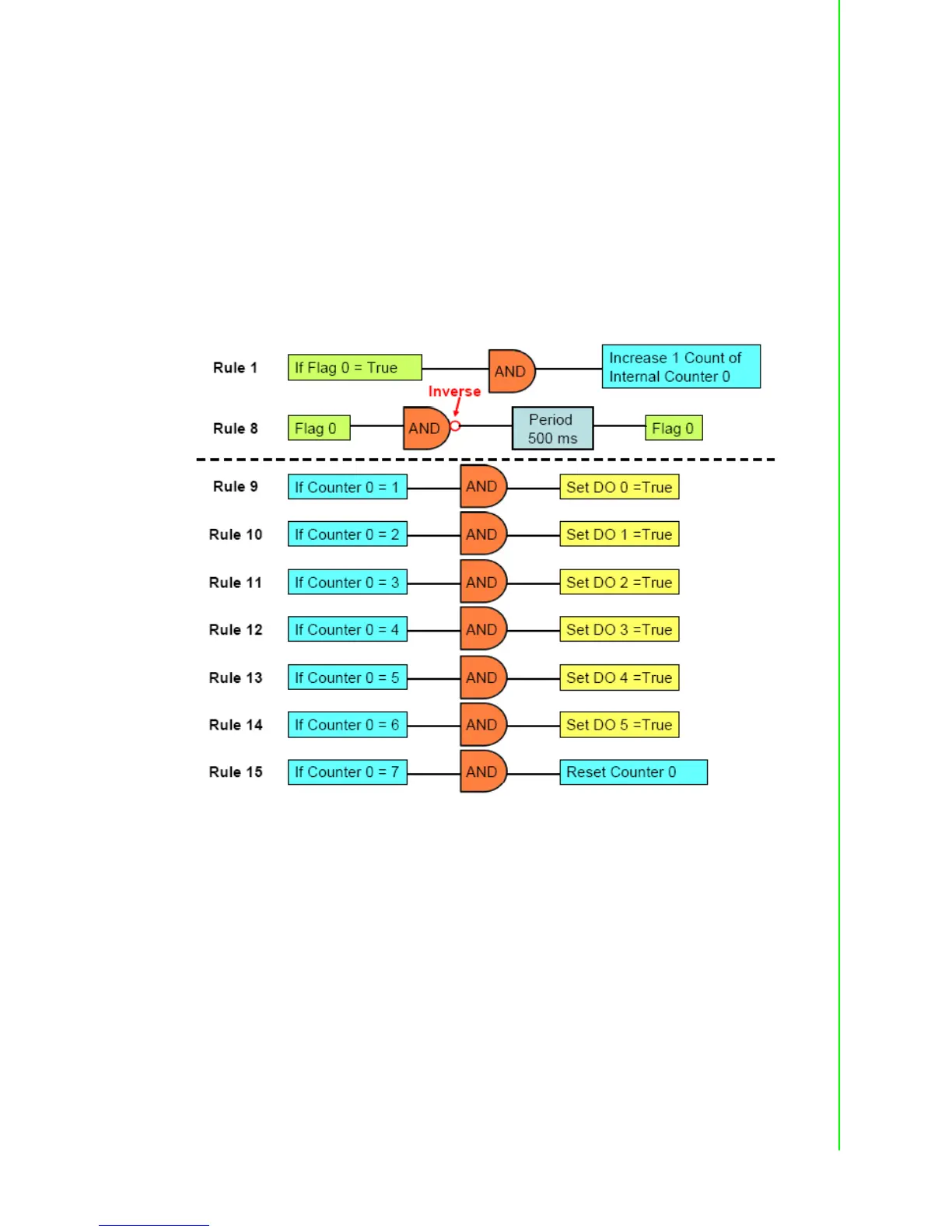
In order to implement this kind of application, 9 logic rules, 1 Internal Counter (Coun-
ter 0) and 1 Internal Flag (Flag 0) are used. In the example project we provide, logic
rule 1 and 8 are used to create the time base. By logic rule 8, Flag 0 value will
change every 0.5 second. In logic rule 1, once the Flag 0 value is logic high, the
Counter 0 will increase 1 unit. So every 1 second, Counter 0 will increase 1 unit, mak-
ing Counter 0 the time base.
Logic rules 9 ~ 14 are used to control DO 0 ~ 5. Which logic rule should be executed
is based on Counter 0 value. Since Counter 0 value will continuously add 1 unit every
1 second, logic rules 9 ~ 14 will be executed in sequence every 1 second. Therefore,
DO 0 ~ DO 5 will be activated sequentially in 1 second. When logic rule 15 is exe-
cuted, Counter 0 will reset and its value will back to zero. So it makes the logic rules
execution become a continuous loop. You can refer its GCL architecture as below.

 Loading...