EasyManua.ls Logo

Advantech ADAM-6251 User Manual

Advantech ADAM-6251
192 pages
To Next Page IconTo Next Page
To Previous Page IconTo Previous Page
Page #122 background imageLoading...
Page #122 background image
ADAM-6200 User Manual 116
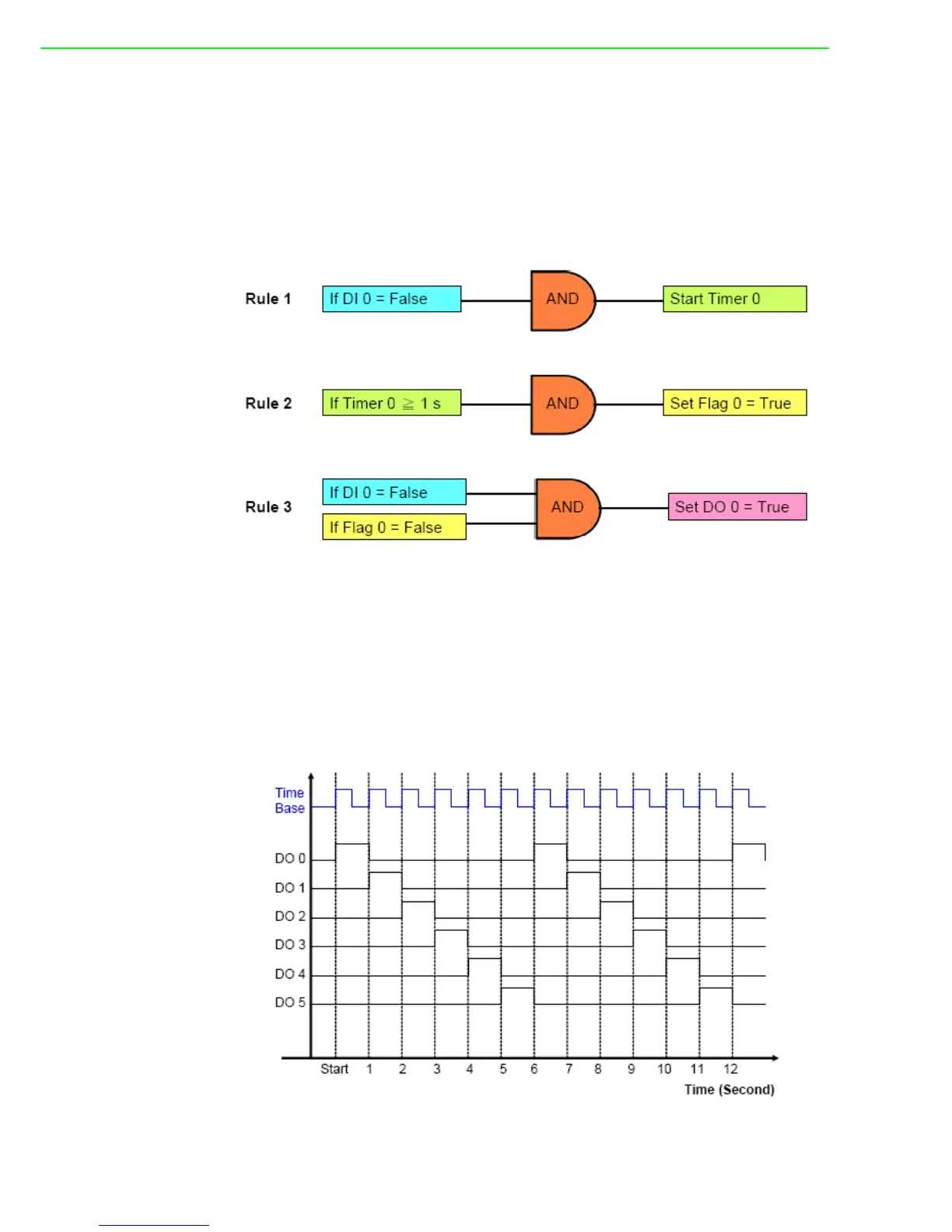
When you use GCL to achieve falling edge application, 3 logic rules, 1 Internal Timer
(Timer 0) and 1 Internal Flag (Flag 0) are needed. For example, with logic rule 3, DO
0 value is controlled by DI 0 and Flag 0. Flag 0 value is logic False at beginning.
When falling edge occurs (DI value changes from logic high to logic low), DO will be
activated (logic rule 3 are satisfied), and Timer 0 starts to count time (logic rule 1 are
satisfied). After Timer 0 counts up to the specific time interval (1 second), Flag 0 will
become logic True by logic rule 2, making DO 0 value logic low (logic rule 3 are not
satisfied). The GCL architecture is similar to the ladder diagram.
8. Sequential Control (Turn On and Off in Sequence Continuously)
This type of automation application is similar to the 3rd application we have intro-
duced. They are both sequential control applications. For example 3, DO channel will
keep its value after it is turned on. In example 8 here, after DO channel is turned on,
it will be turned off after a specific time. You can see the time chart for this application
as below. There is one time base needed to control the digital output sequential
action. In this example, the period of the time base to turn off one DO and turn on the
next-door DO is 1 second.

Table of Contents

Other manuals for Advantech ADAM-6251

Question and Answer IconNeed help?

Do you have a question about the Advantech ADAM-6251 and is the answer not in the manual?

Advantech ADAM-6251 Specifications

General IconGeneral
ModelADAM-6251
CategoryControl Unit
Digital Input Channels8
Digital Output Channels8
Communication InterfaceEthernet
Power Input10 ~ 30 VDC
Digital Input TypeSink/Source
Input TypeDry Contact
Output TypeSink
ProtocolsModbus TCP
Humidity10 ~ 90% RH (non-condensing)
Input Voltage10 ~ 30 VDC

Summary

Safety Instructions

Chapter 1 Product Overview

1.2 Feature Highlights

Key features of the ADAM-6200 series, including installation and management.

Chapter 2 Product Specifications

2.2 Analog Input Module (ADAM-6217)

Details the specifications for the ADAM-6217 8-channel analog input module.

2.3 Analog Output Module (ADAM-6224)

Details the specifications for the ADAM-6224 4-channel analog output module.

2.4 Digital Input/Output Modules (ADAM-6250/6251/6256)

Details specifications for digital I/O modules like ADAM-6250, 6251, and 6256.

2.5 Relay Output Modules (ADAM-6260/6266)

Details specifications for relay output modules like ADAM-6260 and ADAM-6266.

Chapter 3 Hardware Installation

3.2 Mounting

Covers methods for mounting the ADAM-6200 modules in different environments.

3.3 Wiring & Connections

Provides essential information on wiring power supply, I/O units, and Ethernet connections.

3.3.1 Power Supply Wiring

Guides on connecting the power supply to the ADAM-6200 module.

3.3.2 I/O Units

Offers considerations for connecting field devices to the I/O units via terminal blocks.

Chapter 4 System Configuration

4.1 ADAM.NET Utility (software)

Introduces the ADAM.NET Utility software for configuring and monitoring modules.

4.2 Connection

Outlines the steps for connecting the ADAM-6200 module to a computer.

4.3 Configure ADAM-6200 with ADAM.NET Utility

Details the process of configuring the ADAM-6200 module using the ADAM.NET Utility software.

4.3.2 General Configuration

Covers general configuration settings for the ADAM-6200 module within the utility.

4.3.2.2 Network

Details how to configure network settings, including IP address and port configurations.

4.3.2.4 Administration

Covers password management, factory reset, and module restart functions.

4.3.3 I/O Configuration

Details how to set up I/O channel configurations, including range, calibration, and alarms.

4.3.3.1 ADAM-6217

Specific I/O configuration for the ADAM-6217 analog input module.

4.3.3.2 ADAM-6224

Specific I/O configuration for the ADAM-6224 analog output module.

4.3.3.3 ADAM-6250

Specific I/O configuration for the ADAM-6250 digital input/output module.

4.3.3.4 ADAM-6251

Specific I/O configuration for the ADAM-6251 digital input module.

4.3.3.5 ADAM-6256

Specific I/O configuration for the ADAM-6256 digital output module.

4.3.3.6 ADAM-6260

Specific I/O configuration for the ADAM-6260 relay output module.

4.3.3.7 ADAM-6266

Specific I/O configuration for the ADAM-6266 relay output module.

4.3.4 Peer to Peer

Explains the Peer-to-Peer function for direct module-to-module communication.

4.3.5 GCL

Introduces the Graphic Logic Condition (GCL) feature for standalone control.

4.3.5.3 Basic Logic rule programming

Details the process of programming basic logic rules, including Input Condition and Logic stages.

4.3.6 Remotely Monitoring and Control via Web Server

Guides on how to remotely monitor and control modules via a web server using smart devices.

Appendix A I/O Modbus Mapping Table

Appendix B ADAM-6200 ASCII Commands

Related product manuals