AIMB-581 User Manual 4
1.4 Jumpers and Connectors
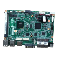
Connectors on the AIMB-581 motherboard link it to devices such as hard disk drives
and a keyboard. In addition, the board has a number of jumpers used to configure
your system for your application.
The tables below list the function of each of the board jumpers and connectors. Later
sections in this chapter give instructions on setting jumpers. Chapter 2 gives instruc-
tions for connecting external devices to your motherboard.
Table 1.1: Jumpers
Label Function
JFP1 Power switch/HDD LED/SMBus/Speaker
JFP2 Power LED and Keyboard lock
CMOS1 CMOS clear (Default 1-2)
PSON1 AT(1-2) / ATX(2-3) (Default 2-3)
JWDT1+JOBS1 Watchdog Reset and OBS Alarm
JCASE1 Case Open pin header
JLVDS1
Voltage 3.3V/5V/12V selector for LVDS1 connector
(Default 1-2, 3.3V)
JLVDS_CLT1
Brightness control selector fo A alog or Digital
(Default 1-2, Analog)
JEME1 Intel AMT Disable Jumpe
JMECLR1 Clear AMT setting
JUSBPWR1 USB port 1~4 power source switch between +5Vsb and +5V
JUSBPWR2 USB port 5/6/7 8 power source switch between +5Vsb and +5V
JUSB PWR3 USB port 9/ 0/11/12 power source switch between +5Vsb and +5V
Table 1.2: Connectors
Label Function
LPT1 Parallel port, supports SPP/EPP/ECP mode
LVDS1 LVDS1 connector
INV1 LVDS1 inverter connector
COM3456 Serials port connector (RS-232)
USB56 USB port 5, 6 (on board)
USB 8 USB port 7, 8 (on board)
USB910 USB port 0, 10 (on board)
USB1112 USB port 11, 12 (on board)
VGA1+DVI1 VGA and DVI connector
COM12 Serial port connector(RS232)
KBMS1 PS/2 Keyboard and Mouse connector
CPUFAN1 CPU FAN connector(3-pin)
SYSFAN1 System FAN1 connector(4-pin)
SYSFAN2 System FAN2 connector(4-pin)
SYSFAN3 System FAN3 connector(4-pin)
SYSFAN4 System FAN4 connector(4-pin)
LAN1_USB12 LAN1 / USB port 1, 2
LAN2_USB34 LAN2 / USB port 3, 4