57 Appendix C
C.13 A/D Control — BASE+09H
Read/write register BASE+09H provides information on the PCL-
818HD/HG/L's operating modes.
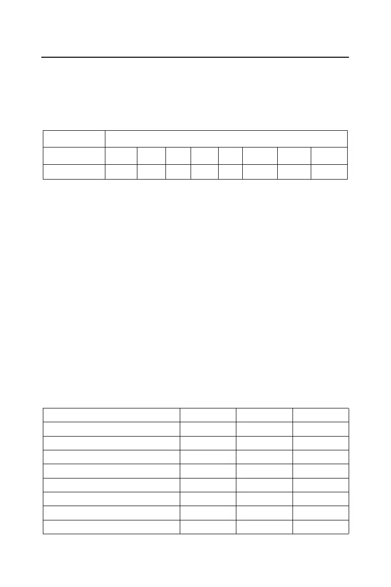
Table C-13 Register for A/D Control
INTE Disable/enable generated interrupts
0 Disables the generation of interrupts. No interrupt signal can
be sent to the PC bus.
Enables the generation of interrupts. If DMAE = O the PCL-818HD/HG/
L will generate an interrupt when it completes an A/D conversion. Use
this setting for interrupt driven data transfer.
If DMAE = 1 the PCL-818HD/HG/L will generate an interrupt when it
receives a T/C (terminal count) signal from the PC's DMA controller,
indicating that a DMA transfer has completed. Use this setting for DMA
data transfer. The DMA transfer is stopped by the interrupt caused by the
T/C signal. See DMAE below.
I2 to I0 Selects the interrupt used by an interrupt or DMA driven data
transfer.
Read/Write A/D control
Bit # 7 6 5 4 3 2 1 0
BASE + 09H INTE I2 I1 I0 DMAE ST1 ST0
Interrupt level I2 I1 I0
N/A 0 0 0
N/A 0 0 1
IRQ2 0 1 0
IRQ3 0 1 1
IRQ4 1 0 0
IRQ5 1 0 1
IRQ6 1 1 0
IRQ7 1 1 1


 To Next Page