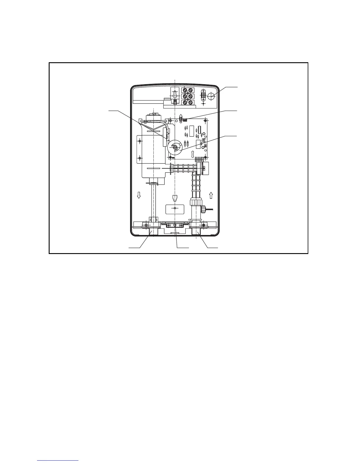
Fig 7
5 6
16
4
3
2
1
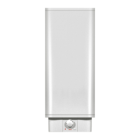
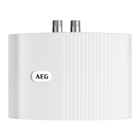
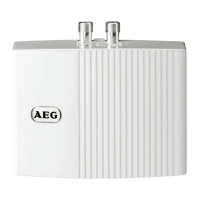
Unit structure
7
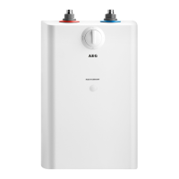
2.1 Technical description
Fig. 7
1. Thermostat
2. Cable duct for electrical
connection
3. Power light
4. Rotary control for
temperature adjustment
5. Hot water connection for
shower hose
6. Cold water connection
Fig. 2
7. Lower xing hole
8. Position for electrical
connection, concealed
9. Upper xing hole
Fig. 3
10. Depth for mounting screw
11. Rear wall installation
Fig. 5
12. Combination lter/seal
13. Washer
14. Water valve
15. Union nut (provided by client)
Fig. 7
16 ELSD (option)
2. Operating instructions for the qualitied installer