30
2. Installation instructions
2.1 Regulations and specifications
●
Installation and electrical connection must be performed by a specialist technician in compliance
with these installation instructions.
●
All electrical connection and installation work must be performed in accordance with the VDE
regulations (0100), specifications from the responsible power supply company and the relevant
national and regional regulations.
●
See the information and materials enclosed in the device packaging.
●
Observe the information on the device rating plate.
The specified voltage must be identical to the mains voltage.
2.2 Technical specifications
Nominal voltage 200-230 V +10 % / -15 % AC 50/60 Hz
Power consumption 3.0 VA
ED system Setting range 30 to 100 %, or “EL”
Max. load Z1/Z2 - 300 W
Switching capacity SH 100 VA / cos ϕ 0,5
Fuse T 1.6 L 250 V
Ambient temperature range 0 °C to +50 °C
Degree of protection IP 20 (after installation)
Safety class II (total insulation)
DIN atmospheric sensor:
Resistance values See page 24
Degree of protection IP 54
Safety class II
Ambient temperature range –40 °C to +50 °C
Connecting cable 2 x 0.75 mm
2
, approx. 1.4 m long
(cable length between sensor and ELFAMATIC µC 3000:
max. 30 m – shielded cables required for longer lengths)
Dimensions ∅ 11,5 x 35 mm
2.3 Installation
2.3.1 Controller
The ELFAMATIC µC 3000 must be fitted in the bottom row of a distribution board, whereby a gap
of one SI circuit-breaker width must be provided at the sides.
Shock protection to safety class II is provided if the ELFAMATIC µC 3000 is installed in
●
a small distribution board to DIN or
●
a distribution board to DIN
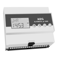
The ELFAMATIC µC 3000 consists of a base with terminals
for rail mounting as well as the plug-in housing with the
electronic components.
The top part of the housing is removed from the base by
releasing the lower housing catch using a screwdriver and
then pulling off the top part.
The base must be de-energised before the top part of
the housing is mounted.
ELFAMATIC c3000m
M
P
+
–
For the Fitter
 Loading...