AA80 InterVOX Intercom Systems
SM08 Installation and Operation Manual
April 30, 2012 Rev: 5.00 Page 2-2
ENG-FORM: 805-0100.DOTX
CONFIDENTIAL AND PROPRIETARY TO ANODYNE ELECTRONICS MANUFACTURING CORP.
2.3.3 NOTES
The “Operations“ section of this manual (3.0) can be used to provide additional reference material for
system users.
2.3.4 Cabling and Wiring
All unshielded wire shall be selected in accordance with the original aircraft manufacturer’s maintenance
instructions or AC43.13-1B Change 1, Paragraphs 11-76 through 11-78. Wire types should be to MIL-W-
22759 as specified in AC43.13-1B Change 1, Paragraphs 11-85, 11-86, and listed in Table 11-11. For
shielded wire applications, use Tefzel MIL-C-27500 shielded wire with solder sleeves (for shield
terminations) to make the most compact and easily terminated interconnect. Follow the wiring diagrams in
Section 2.9 as required.
Installation cabling must allow the unit to be easily withdrawn for disconnection, switch and pot settings
(internal), and removal. Ensure an adequate service loop is allowed in the routing of the cable. This can
become a serious problem if the unit is installed with the cables so short that the unit cannot be removed
without disassembly of the mounting console. At least 1 foot (30 cm) of free cable is recommended.
Allow 3 inches (8 cm) from the end of the wire to the shield termination to allow the hood to be easily
installed. Note that the hoods supplied by AEM in installation kits are 'clamshell' hoods, and are installed
after the wiring is completed.
Generally, all wiring should be at least 22 AWG, except power and ground connections, which should be
20 AWG - check the appropriate Interconnect drawing for the unit under consideration. Ensure that the
ground connection is clean and well secured. To prevent inadvertent system failure, power to this system
must be supplied from a separate breaker or fuse, and not bundled to any other source. A ½ A breaker is
suggested (28 Vdc source).
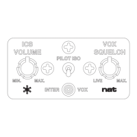
2.3.5 Mechanical Mounting
If the InterVOX will be installed in a standard clock hole, no holes need to be drilled, as the unit will mount
directly into the existing hole pattern. If horizontal or vertical mounting with a rectangular faceplate is
desired, check the drilling template in figure 2.41. Note that the mounting nuts for the panel pots ARE
NOT REMOVED AT ANY TIME. Clearance hole should be drilled (3/8”), so that they will fit into the
instrument panel. The AA80 can be mounted in a standard instrument hole by using the AA80-SQR
adapter plate.
The template can be fastened directly to the instrument panel, and the holes drilled through the indicated
locations. An Allen key is required to remove the knobs from the pots prior to mounting. The unit is held in
place with three black Phillips screws (supplied), which require 5/32” panel holes.