34
Durante il funzionamento delle unità a pompa di calore
viene periodicamente scaricata dell’acqua (durante la fase
di sbrinamento) nella parte inferiore dell’unità.
Se tale acqua dev'essere convogliata per lo scarico sarà
necessario prevedere una bacinella di raccolta munita di
foro di scarico.
COLLEGAMENTI ELETTRICI
L'unità è completamente cablata in fabbrica e per la messa
in funzione necessita dell'alimentazione elettrica secondo
le indicazioni sulla targhetta caratteristica dell'unità, inter-
cettata con delle protezioni in linea.
Tutti i collegamenti elettrici devono essere rispondenti alle
norme legislative locali vigenti al momento dell'installazione.
Gli schemi riportati nella seguente documentazione devono
essere utilizzati solo come ausilio per la predisposizione
delle linee elettriche. Per le necessità di installazione, fare
riferimento allo schema elettrico fornito con l'apparecchio.
Solo per versioni trifase:
Per un corretto funzionamento del compressore, rispettare
la sequenza R S T della linea d’alimentazione. Un’elevata
rumorosità è indice di un errato collegamento delle fasi
d’alimentazione.
Nel caso s’installino degli interruttori per il comando a
distanza, i collegamenti alla morsettiera dell’unità devono
essere realizzati utilizzando cavi schermati.
La distanza max. consentita è di 30 m, oltre tale distanza si
consiglia l’utilizzo degli accessori PRI o PR1 e SDP (distan-
za massima = 150m).
ATTENZIONE:
Solo per le unità a pompa di calore sulle quali non si voglia
installare interruttori remoti per comandarne il funziona-
mento a distanza.
Siccome le unità della serie AN partono predisposte dalla
fabbrica per poter essere comandate anche da pannelli
remoti o da semplici interruttori (per esempio interruttori
acceso/spento, caldo/freddo...), solamente le unità a pompa
di calore necessitano di una riprogrammazione dei dati
contenuti nella scheda elettronica.
N.B. = se non si effettua tale operazione, non si sarà in grado, solo
dal pannello a bordo macchina, di commutare l’unità dal funziona-
mento invernale a quello estivo o viceversa.
Procedere come segue:
– premere contemporaneamente i tasti SEL e PRG per alme-
no 5 secondi (sul display compare il valore 0);
– mediante i tasti freccia modificare il valore a display sino
ad avere la scritta 177;
– premere il tasto SEL; a display compare la scritta /3;
– mediante i tasti freccia modificare il valore a display sino
ad avere la scritta P8;
– premere il tasto SEL; a display compare la scritta 7;
– mediante i tasti freccia modificare il valore a display sino
ad avere 0;
– rendere definitive le modifiche premendo il tasto PRG.
During operation of the heat pump models, the water pro-
duced during the defrosting cycle is removed through the
bottom side of the unit.
If necessary, convey the water towards a drip tray with
drain pipe.
WIRING CONNECTIONS
The unit is completely factory wired; to power the unit, refer
to the specifications on the data plate on the unit. Install
current cut-out switches.
All electrical connections must comply with current safety
standards when the unit is installed.
The diagrams in the following documentation are indicative
only of electrical connections. When installing, refer to the
electrical diagrams supplied with the machine.
Only for three-phase versions:
Follow the sequence R S T of the feeding line to perform a
proper operation of the compressor. A hight noise level is
the sign of a wrong connection of the phases.
If switches are installed for remote control, the connections
to the unit terminal board must be made using screened
cables.
The max. permitted distance is 30 m, above this distance
use of the accessories PRI or PR1 and SDP is recommended
(maximum distance = 150m).
IMPORTANT:
Applies only to heat pumps to be installed without remote
control panels.
AN series units are prearranged for remote control or opera-
tion by switch (e.g. ON/OFF, warm/cool); for this reason,
only heat pump units require electronic panel reprogram-
ming.
N.B. This operation is necessary to ensure correct switcho-
ver between summer and winter cycle operation from the
front panel.
Proceed as follows:
– press and hold keys SEL and PRG for at least 5 seconds
(display will show a value of 0);
– by means of the arrow keys, set the displayed value to
177;
– press SEL; the message /3 will appear;
– by means of the arrow keys, set the displayed value to P8;
– press SEL; the number 7 will be displayed;
– by means of the arrow keys, set the displayed value to 0;
– press PRG to confirm the modifications.
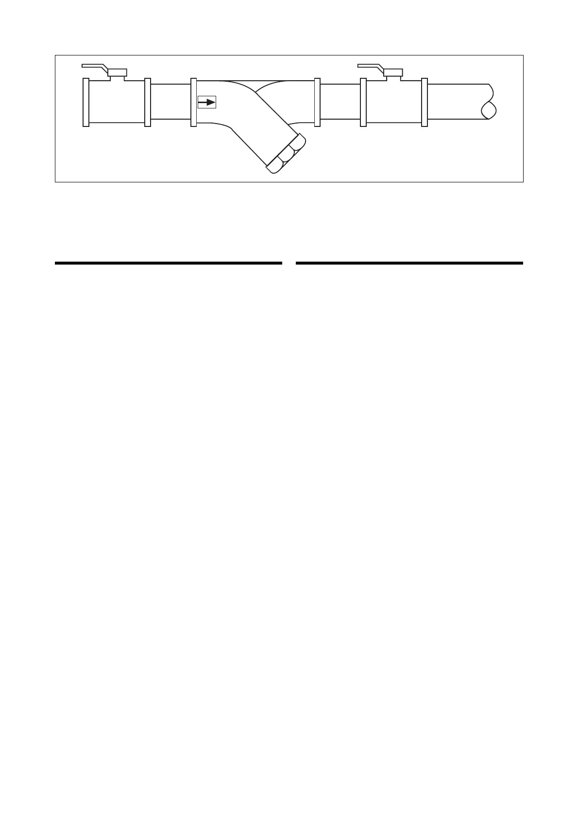
Allo scambiatore
To heat exchanger
 Loading...