EN
21.11 - 6755517_05
19
13.
STORAGE TANK
The following tables highlight principle char-
acteristics for hydraulic circuit components,
whilst the graph on the following page
shows relative static pressures.
13.1.
SYSTEM WATER
The minimum water content of system recommended
for units without hydronic kit is calculated using follow-
ing formula:
x 4
PFN: Nominal cooling capacity
That resulting minimum water content necessary for
correct function of system.
The adjacent table indicates maximum water capac-
ity in litres of hydraulic plant, compatible with expan-
shown in the table refer to three maximum and
minimum water temperatures. If the effective water
content of the hydraulic plant (including the storage
-
tional conditions, another dimensioned expansion
vessel must be installed, using thenormal criteria,
with reference to the additional volume of water.
In the following tables it is possible to work out the
maximum values of the system also for glycoled
water functioning.
value by the corrective coefficient.
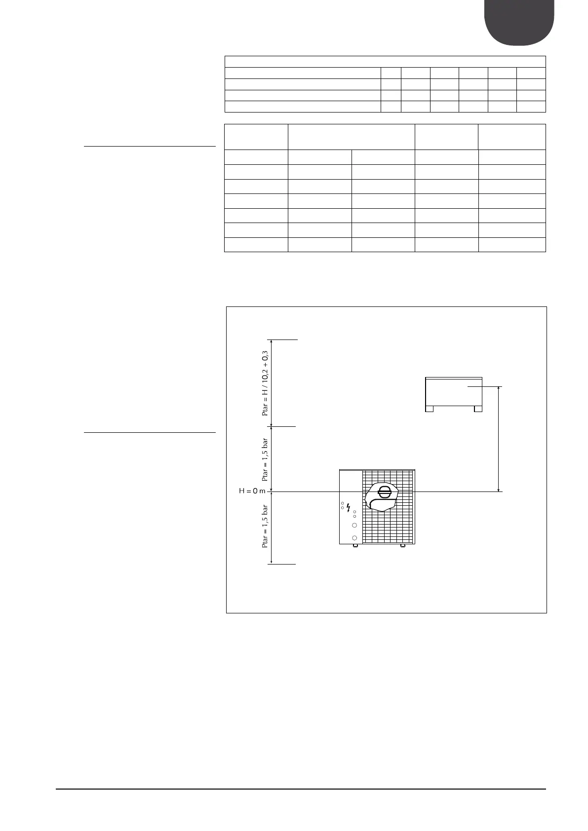
13.2. EXPANSION VESSEL CALIBRATION
Standard pre-load pressure value of expansion
vessel when empty is 1.5 bar, maximum value is
6 bar.
Calibration of the vessel must be regulated using the
by using the following formula:
calibration value of the vessel will be 2.3 bar.
If calibration value obtained from formula is less than
standard.
Hydraulic height
30 25 20 15
Calibration of expansion vessel bar 3.2 2.8 2.3 1.8 1.5
Water content reference values l
257 303 348 394 419
Water content reference values l
116 136 157 177 189
Corrective
coefficients
conditions
max. min.
10% 40 -2 0,507
10% 60 -2 0,686
20% 40 -6 0,434
20% 60 -6 0,604
35% 40 -6 0,393
35% 60 -6 0,555
Recommended operational conditions:
KEY
Check that highest installa-
tion is not higher than 55
metres.
-
lation can withstand global
pressure in that position.