English
28
IFCLIJ 1107 - 4528500_04
- Choose where to install the machine
according to the layout of the room,
the number of units to be installed
and any limitations imposed by the
architecture. Check that installation
and maintenance of the machine is
possible in the position chosen.
- Install four M8 threaded rods into the
ceiling to hold the frame.
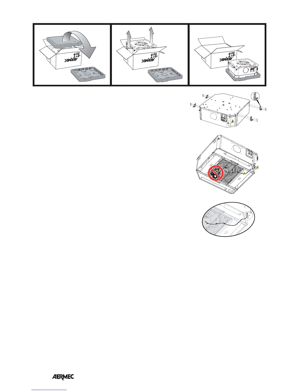
Proceed as follows to install the FCL
unit:
- Open the cardboard package.
- Overturn the FCL cassette fan coil box.
- Remove the box.
- Remove the packaging shells used to
protect the unit during transport.
- Apply the 4 installation brackets all’
unit. (see figure)
- If necessary, mount any accessories
(electric resistances, fresh air kit or flow
to adjacent room, hot water valve).
Carry out these operations before
installing the unit on the ceiling.
ATTENTION: consult the accessory
manuals.
- Do not handle the unit using the
hydraulic connections but use the
brackets.
- Lift the unit carefully using the brackets
and holding it slightly inclined. Fix it
to the 4 threaded rods using the 8 nuts
of which 4 are self-locking. Act on the
nuts to adjust the height, finally check
that the unit is installed in a horizontal
position.
- Feed the hydraulic lines through the
suspended-ceiling to the attachment
plate on the unit;
- Make the hydraulic connections as
described in the relative chapter.
- Take the condensate drain pipe to the
respective fitting on the attachment
plate;
- Connect the condensate drain as
described in the relative chapter.
- Bleed the system, the vent valves are
external on the connections plate.
- Take the electric power supply cables
and control cables in proximity of
the electric box; make sure that the
cables are long enough to follow
the movement of the electric box on
the guides during the assembly and
disassembly phases.
- The electric box is supplied with grid
accessories (GLL20 and GLL20R)).
- Consult the grid accessory manuals.
The instructions for mounting and
connection of the electric box are
contained in the manual supplied with
the accessory.
- After having completed the
connections and the electric box is
inserted in its housing in the FCL unit,
fix it using the two screws.
- For GLL20R only: apply any air probe
(SA) to the centre of the fan grid, fix the
cable using the supplied straps, lay the
excess cable in the grooves made in
the polystyrene.
- The grill frame must be positioned in
a way that the AERMEC logo holder
corresponds with the corner of the
electric box.
- Fix the grid using the 4 screws.
ATTENTION!! tighten the screws
with maximum coupling torque
of 0.45 Nm. It is advised to use a
screwdriver, do not use non calibrated
electric screwdrivers. An excessive
coupling torque will damage the tray
irreparably.
- ATTENTION: fix a safety cable snap
hook must then be attached to the grid
frame and the other snap hook to the
fan protection grid.
- Fix the intake grill to the safety cable.
- For GLL20R only: make the
connections between the electric box
and the receiver.
- Adjust the position of the unit by the
support brackets by means of the nuts,
in a way that the unit is level and the
frame rests slightly on the suspended
ceiling.
- Start the fan coil and carry out a
functioning test. The functions are
described in the user manual.
INSTALLATION OF THE "MODULE 840" UNIT
SA
SA