English
22
IFCLIJ 1107 - 4528500_04
Average minimum temperature of the water
If the fan coil functions continuously in
cooling mode inside a room with high
relative humidity, condensate may form
on the air flow and outside the applian-
ce. This condensate, could deposit on
the floor and any other objects.
To prevent condensate forming on the
external structure of the appliance with
fan running, the average temperature
of the water must not be lower than the
limits stated in the table below, which
depend on the thermo-hygrometric con-
ditions of the environment air.
These limits refer to functioning with the
fan running at minimum speed.
TECHNICAL DATA AND FUNCTIONING LIMITS
The performance refers to the following conditions:
- at maximum motor speed;
- the total power absorbed is given by the sum of the power ab-
sorbed by the unit and the power absorbed by the accessories
and declared in the relative manuals.
Water temperature
In order to prevent stratification of the air in
the room, and therefore have better mixing,
it is recommended not to power the fan coil
with water hotter than 65°C.
The use of water with high temperatures
can cause small creaks due to the different
heat dilations of the elements (plastics
and metals). This however does not cause
damage to the unit if the maximum
working temperature is not exceeded.
PURPOSE OF THE UNIT
The fan coil is a terminal for treating air in a room in the winter and
summer seasons.
FCL version
Cassette type fan coil for suspended-ceiling installation.
DESCRIPTION OF THE UNIT
SIZES AVAILABLE
The cassette fan coils in the FCL range are available in two fundamental dimensions that are called "Modules"
For two-pipe systems
8 sizes
For four-pipe systems
7 sizes
• Standard FCL set-up with internal
3-way valve as per standard with quick-
fi tting actuator and visual position signal.
• The FCL_V2 set-up, with 2-way internal
valve as per standard with quick-fi tting
actuator and visual position signal,
suitable for variable water fl ow rate
systems.
• The FCL_VL set-up, without internal
valve.
SET-UPS
The cassette fan coils are available in
three set-ups, in order to satisfy all system
requirements.
The sizes, performance and external
dimensions are the same as the standard
FCL set-up.
In this manual the FCL_VL and FCL_V2
set-ups will only be recalled where there
are differences with respect to standard
FCL versions, otherwise they will be
simply called FCL. The FCL_VL and FCL_
V2 set-ups are available on request.
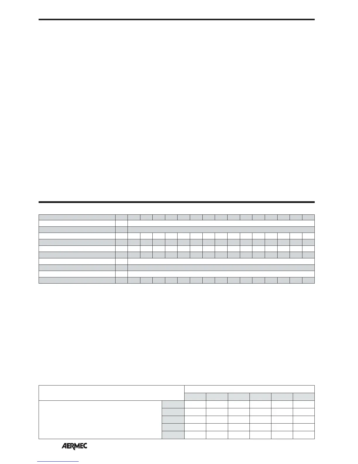
AVERAGE MINIMUM TEMPERATURE OF THE WATER [°C]
Dry bulb temperature of the room temperature [°C]
21 23 25 27 29 31
Wet bulb temperature
of the room air [°C]
15 333333
17 333333
19 333333
21 654333
23 -87655
FCL 32 (Module 600)
FCL 36 (Module 600)
FCL 42 (Module 600)
FCL 62 (Module 600)
FCL 72 (Module 600)
FCL 82 (Module 840)
FCL 102 (Module 840)
FCL 122 (Module 840)
FCL 34 (Module 600)
FCL 38 (Module 600)
FCL 44 (Module 600)
FCL 64 (Module 600)
FCL 84 (Module 840)
FCL 104 (Module 840)
FCL 124 (Module 840)
FCL 32 34 36 38 42 44 62 64 72 82 84 102 104 122 124
Maximum water inlet temperature [°C] 80
Maximum operating pressure [bar] 8
Minimum water flow rate (heating) [l/h] 100 50 100 50 100 50 150 50 150 250 50 350 50 350 50
Maximum water flow rate (heating) [l/h] 750 400 750 400 750 400 1050 400 1050 1750 400 2450 400 2450 400
Minimum water flow rate (cooling) [l/h] 100 100 100 100 100 100 150 150 150 250 250 350 250 350 250
Maximum water flow rate (cooling) [l/h] 750 750 750 750 750 750 1050 1050 1050 1750 1750 2450 1750 2450 1750
Room temperature limits (Ta) [C°] 0 < Ta < 40
Relative humidity limits in the room R.H. U.R. < 85%
Power supply 230V ( ±10% ) ~ 50Hz
Total input power [W] 45 45 45 45 75 75 83 83 93 150 150 155 155 175 175