11
4 CONTROL LOGIC
The table below highlights the control logics enabled for each heat recovery unit functioning mode:
FUNCTION
FUNCTIONING MODE
Auto Manual Aux
Anti-freeze through ow rate modulation x x x
Anti-freeze through electric resistance x
Freecooling x x
Steriliser lamp activation x x x
Coil control for air post-treatment x x x
Resistance control for air post-treatment x
Room air cleaning function x
CF contact ventilation forcing x x
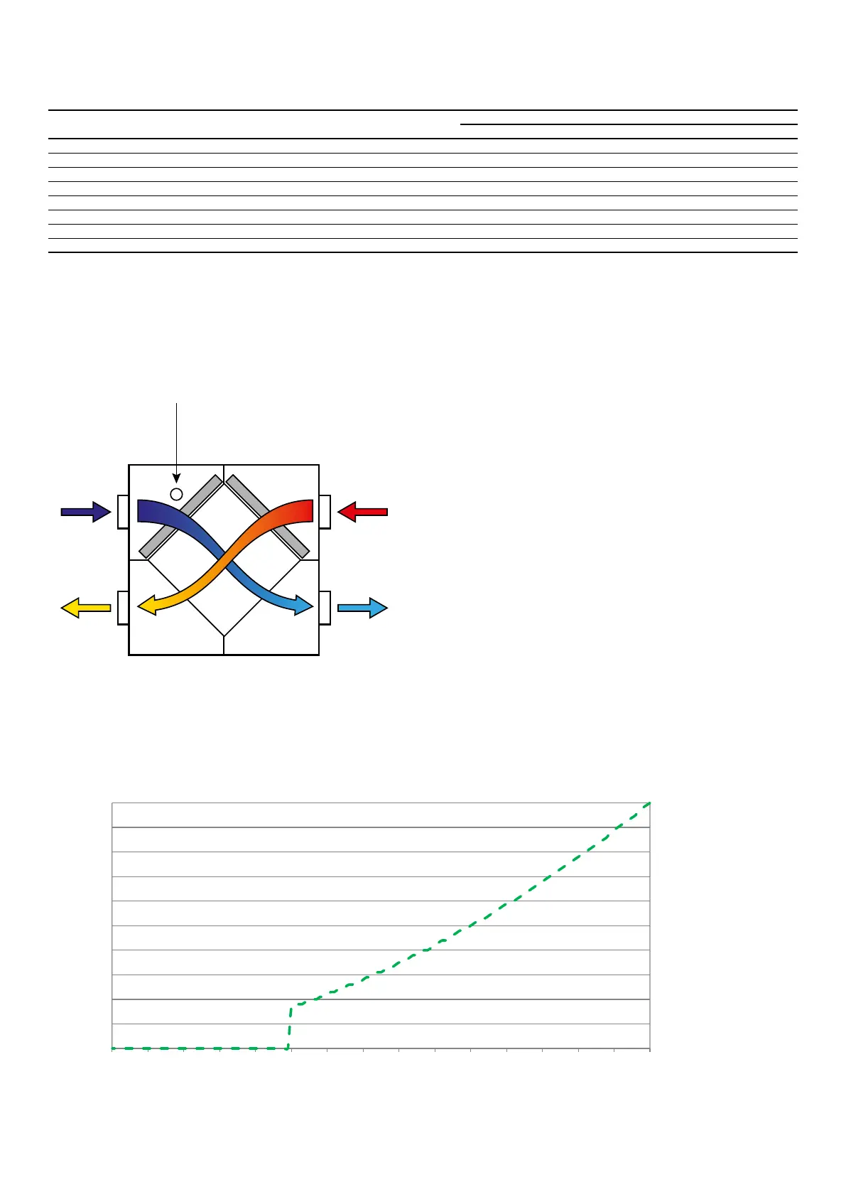
4.1 ANTI-FREEZE THROUGH FLOW RATE MODULATION
During winter functioning, the recovery unit provides for the modulation of the air ow rate introduced so as to prevent the formation of frost in the exchanger and the exten-
sion of the operating limit up to -10 [°C] of outdoor air.
(fresh air)
Indoor air
(recovery)
(spoiled)
Air inlet
(delivery)
The fresh ow rate modulation is functionally linked to the TSAE according to the following relationships:
PI = Po1 * PMAX * Ci(T)
Where “Ci” is the correction of the inlet ow rate in relation to the outdoor air temperature (curve highlighted in the following paragraph)
0
10
20
30
40
50
60
70
80
90
100
15 -14 -13 -12 -11 -10 -9 -8 - 7 -6 -5 -4 -3 -2 -1 0
SAE