5
2 CONNECTIONS
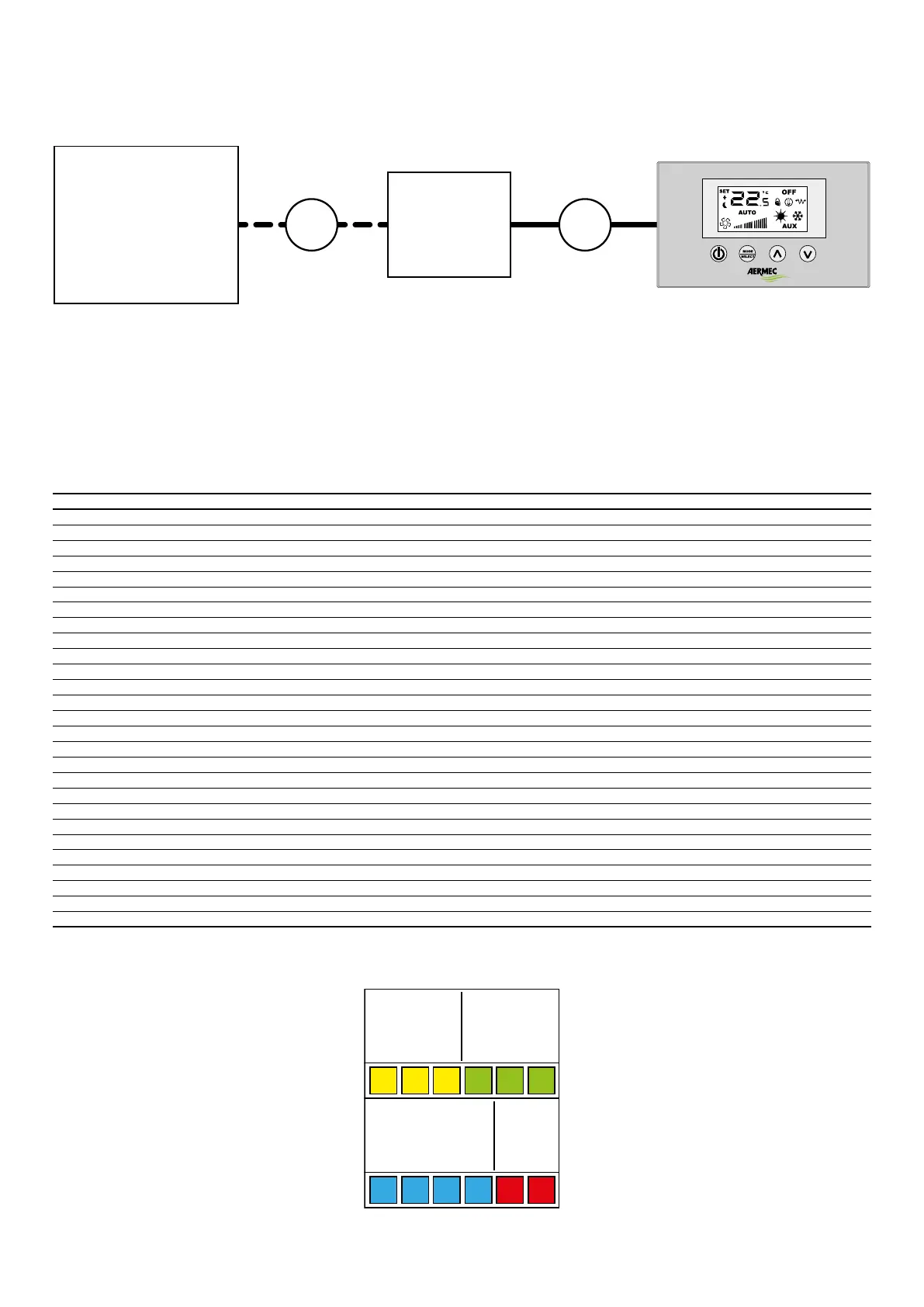
2.1 CONNECTION BETWEEN LOAD CONTROL BOARD AND USER PANEL
RPLi
HRC2 1
Connections:
1: Connection between user panel and load board, to be made with a 4-pole serial cable plus screen (22AWG) supplied;
2: Connection between load board and recovery unit, to be made according to connection needs, following the instructions provided in the next chapter.
Note: the connections from the terminal board (or possible VMF-MOD accessory board) can be 3m max.
2.2 CONTROL BOARD INPUT/OUTPUT
The following tables show the control board input/output: the input/output column indicates the input/output how it is called on the board wiring diagram, the Function
column indicates how the inputs and outputs are used on the various machines in which the board will be installed, the Electrical characteristics column shows the type of
electrical signal that characterises the input/output.
I/O Function Electrical characteristics
M2 L: board electric power supply input Voltage: 230 Vac, 10 A current
M1 N: board electric power supply input Voltage: 230 Vac, 10 A current
M3 GND: ground reference //
M4 AUX/RE: output for electric post-heating resistance control Voltage: 230 Vac, 10 A current
M5 Neutral reference Voltage: 230 Vac, 7 A current
M6 MA: output for freecooling bypass motor control Voltage: 230 Vac, 5 A current
M7 Y2: output for electric post-heating resistance control (second stage) Voltage: 230 Vac, 5 A current
M8 Y1: output for pre heating resistance control Voltage: 230 Vac, 5 A current
M9 Neutral reference Voltage: 230 Vac, 10 A current
M10 Neutral reference Voltage: 230 Vac, 10 A current
M11 V3: output for purication device or output damper control Voltage: 230 Vac, 5 A current
M12 V2: output for VSL valve control (cooling only) Voltage: 230 Vac, 5 A current
M13 V1: output for VSL valve control (heating/cooling or heating only) Voltage: 230 Vac, 5 A current
M14 Support input, not connected //
M26 Service terminal board See gure 4
M22 Terminal board not used //
CN2 SW: SAEXIT water probe (if dip 2 OFF): probe of air expelled to the outside (if dip 2 ON) NTC 10Kohm
CN1 SAE: outdoor air probe NTC 10Kohm
CN3 SAM: probe of air introduced into the room NTC 10Kohm
M15, M16 SA: probe of air expelled from the room NTC 10Kohm
M17 Out 0-10V: reference for air inow inverter fan Voltage: 10 Vdc, 10 mA current
M18 Inverter reference GND Voltage: 10 Vdc, 10 mA current
M19 Out 0-10V: reference for air expulsion inverter fan Voltage: 10 Vdc, 10 mA current
M20 GND Voltage: 10 Vdc, 10 mA current
M21 Not used Voltage: 10 Vdc, 10 mA current
M25 VMF-MOD expansion connector //
M27,M28 MS: dierential pressure switch status input Voltage: 5 Vdc, 0.5 mA current
NOTE: the M26 terminal board integrates dierent specications, for more details refer to the specic table on the next page.
M26 Terminal board specications:
CE
GND
CF
A
B
GND
1 TX/RX
2 GND-TTL
3 MODE
4 V5
5 TX/RX
6
1
2
3
4
5
6GND
TTL