25
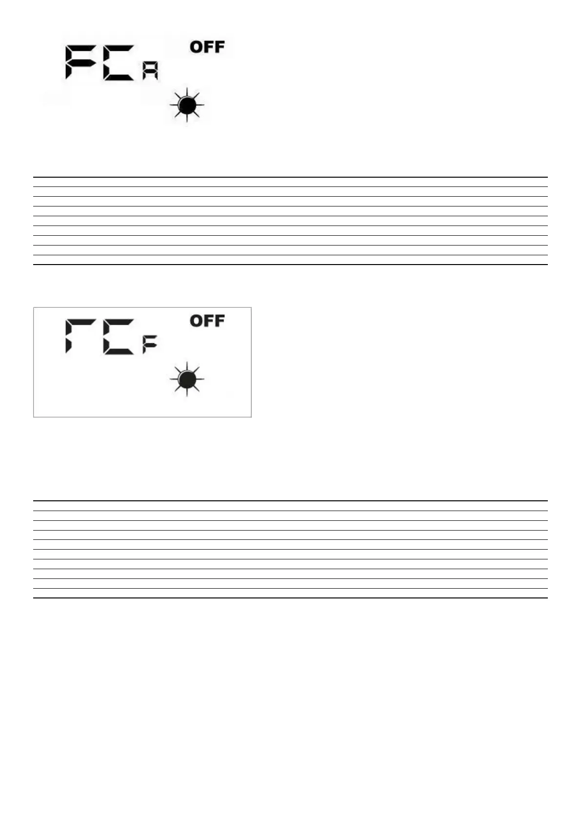
To activate the desired load, the operator must set the associated value (see the table below). The display shows the data set for the entire duration of the forcing (set by default
at 5 seconds). At the end of this time, the FCA value goes back to zero and the load switches o.
FCA Value Load activated for 5 seconds
1 Fan 1 at maximum speed
2 Fan 2 at maximum speed
3 Reset lter func. hours alarm
4 DMP
5 VSL
6 RXPOST
7 RXPRE
8 LAMP
5.10 °C/°C CHANGE MENU
where:
— 0 = °C
— 1 = °F
5.11 ALARMS SIGNAL
The user interface panel shows some system anomalies with an alphanumeric string, the following table contains all the alarm signals foreseen in the system.
Alarm code Description
AL0 No communication between the RepControl board and user interface
AL1 Room air probe present in the faulty interface panel
AL2 Faulty F3 fuse
AL3 Faulty F2 fuse
AL4 Faulty SA probe
AL5 Faulty SAM probe
AL6 Faulty SAE probe
AL7 Faulty anti-freeze damper
AL8 Filter cleaning