7. DESCRIPTION
OF COMPONENTS
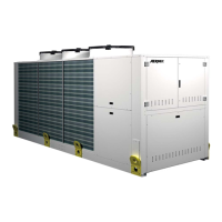
7.1. STRUCTURE
BASEAND SUPPORT STRUCTURE
Made up from hot galvanised sheet steel elements
with suitable thickness. All parts painted with
polyester powder paints (RAL 9002), resistant to
atmospheric agents.
Realised in a way to allow total accessibility to
the components internal components. All panels
are covered with sound-absorbent material with
suitable thickness.
7.2. COOLING CIRCUIT
COMPRESSOR
Hermetic scroll rotary compressors. All compressors
come with casing resistance, electronic thermal
protection with centralised manual resetting and
two-pole electric motor.
COOLING/HEATING EXCHANGER SYSTEM SIDE
Braze welded AISI 316 steel plate heat exchanger,
insulated externally with closed cell neoprene anti-
condensation material. When the unit is not running,
it is protected against formation of ice inside by an
electric resistance.
7.3. WATER FEATURES
PH 6-8
Electric conductivity Less than 200 mV/cm (25°C)
Chloride ions Less than 50 ppm
Sulphuric acid ions Less than 50 ppm
Total iron Less than 0.3 ppm
Alkalinity M Less than 50 ppm
Total hardness Less than 50 ppm
Sulphur ions None
Ammonia ions None
Silicone ions Less than 30 ppm
DHW SIDE HEAT EXCHANGER 2 pipes)
HEATING SIDE SYSTEM 4 pipes)
Braze welded AISI 316 steel plate heat exchanger,
insulated externally with closed cell neoprene anti-
condensation material. When the unit is not running,
it is protected against formation of ice inside by an
electric resistance.
AIR SIDE COIL EXCHANGER
Finned pack heat exchanger made with copper pipes
and aluminium fins adequately spaced to ensure
better heat exchange performance.
CYCLE REVERSING VALVE (2 PIPE)
4-way cycle reversing valve. Inverts the flow of
refrigerant gas.
RECOVERY ENABLE VALVE
4-way valve enables the recovery heat exchanger.
LIQUID STORAGE TANK
(always passed by)
Compensates the difference in volume between
finned coil and plate exchanger, retaining excess
liquid.
LIQUID SEPARATOR
Located on the suction point of the compressor, to
protect against any flowback of liquid refrigerant,
flooded start-ups, operation in the presence of
liquid.
DEHYDRATOR FILTER
Hermetic-mechanical with cartridges made of
ceramic and hygroscopic material, able to withhold
impurities and any traces of humidity present in the
cooling circuit.
ONE WAY VALVES
Allows one-way flow of the refrigerant.
THERMOSTATIC VALVES
Two valves installed:
(cooling mode and recovery mode)
Mechanical valves, with external equaliser
positioned at evaporator outlet, modulates the flow
of gas to the evaporator, depending on the heat
load, in order to ensure a correct heating level of
the intake gas.
SOLENOID VALVES
The valve closes when the compressor switches
off, blocking the flow of refrigerant gas to the
evaporator, recovery and the coil.
INDICATOR FOR LIQUID
Used to check presence of humidity in cooling
circuit.
7.4. STANDARD HYDRAULIC CIRCUIT
WATER FILTERS
Equipped with steel filtering mesh, prevents the
heat exchangers both of the system side and the
DHW/heating system side from clogging.
FLOW SWITCHES
They have the task of controlling that there is water
circulation inside the heat exchangers; if this is not
the case, they block the unit.
AIR VENT VALVE
Mounted on the top of the hydraulic system; they
discharge possible air pockets.
7.4.1. COMPONENTS OF HYDRAULIC CIRCUIT
IN CONFIGURABLE VERSIONS
PUMPS
High or low static pressure.
EXPANSION VESSEL
With nitrogen pre-load membrane.
SAFETY VALVE
Equipped with a piped discharger, intervenes by
discharging the over pressure in case of anomalous
pressures.
SYSTEM STORAGE TANK
Made of steel to reduce heat loss and to eliminate
the formation of condensation, insulated by thick
polyurethane.
DRAIN TAP
7.5. SAFETY AND CONTROL
COMPONENTS
MANUALLY RESET HIGH PRESSURE SWITCH
With fixed calibration, placed on high pressure side
of cooling circuit, inhibits functioning of compressor
if abnormal work pressure occurs.
LOW PRESSURE TRANSDUCER
Placed on the low pressure side of the cooling
circuit, it signals the work pressure to the control
board generating a pre-warning in the case of
anomalous pressures.
HIGH PRESSURE TRANSDUCER
Placed on the high pressure side of the cooling
circuit, it signals the work pressure to the control
board generating a pre-warning in the case of
anomalous pressures.
RELIEF VALVES
They intervene by discharging the overpressure in
the case of anomalous pressures.
- Calibrated at 45 bar on HP branch.
- Calibrated at 30 bar on LP branch.
CONDENSATION PRESSURE CONTROLLER
This device allows correct functioning with external
temperatures lower than 10°C and as low as – 10°C.
It consists of an adjustment circuit board that
varies the number of fan revs according to the
condensation pressure read by the high pressure
transducer, in order to keep it sufficiently high for
correct unit functioning.
It also allows correct functioning in heating mode
with external temperatures exceeding 30°C and up
to 42°C.
7.6. ELECTRIC CONTROL
AND POWER BOARD
Electric board in compliance with standards UL1995,
EN 60204-1/IEC 204-1, complete with:
- transformer for the control circuit,
- door lock main isolating switch,
- fuses and contactors for compressors and fans,
- terminals for REMOTE PANEL,
- spring type control circuit terminal board,
- outdoor electric board with double door and
gaskets,
- electronic controller,
- evaporator pump and recovery pump control
consent relay (only for versions without pump
units),
- all numbered cables.
DOORLOCK ISOLATING SWITCH
The electric control board can be accessed by
removing the voltage. Act on the opening lever of
the control board itself. This lever can be locked
using one or more padlocks during maintenance
interventions to prevent the machine being
powered up accidentally.
CONTROL BOARD
1. Allows the complete control of the appliance.
For a more in-depth description please refer
to the user manual.valve and ON/OFF pumps.
2. Production of DHW through a 3-way diverter
valve or the total recovery version.
Additional functions:
• Control of an external integration
resource dedicated to DHW.
ATTENTION
For questions of space, in configurations
with storage tank and built-in pump/s
on the system side, no pumps can be
available on the recovery side!
11
INRP260HzTY. 1312. 5806717_03
 Loading...