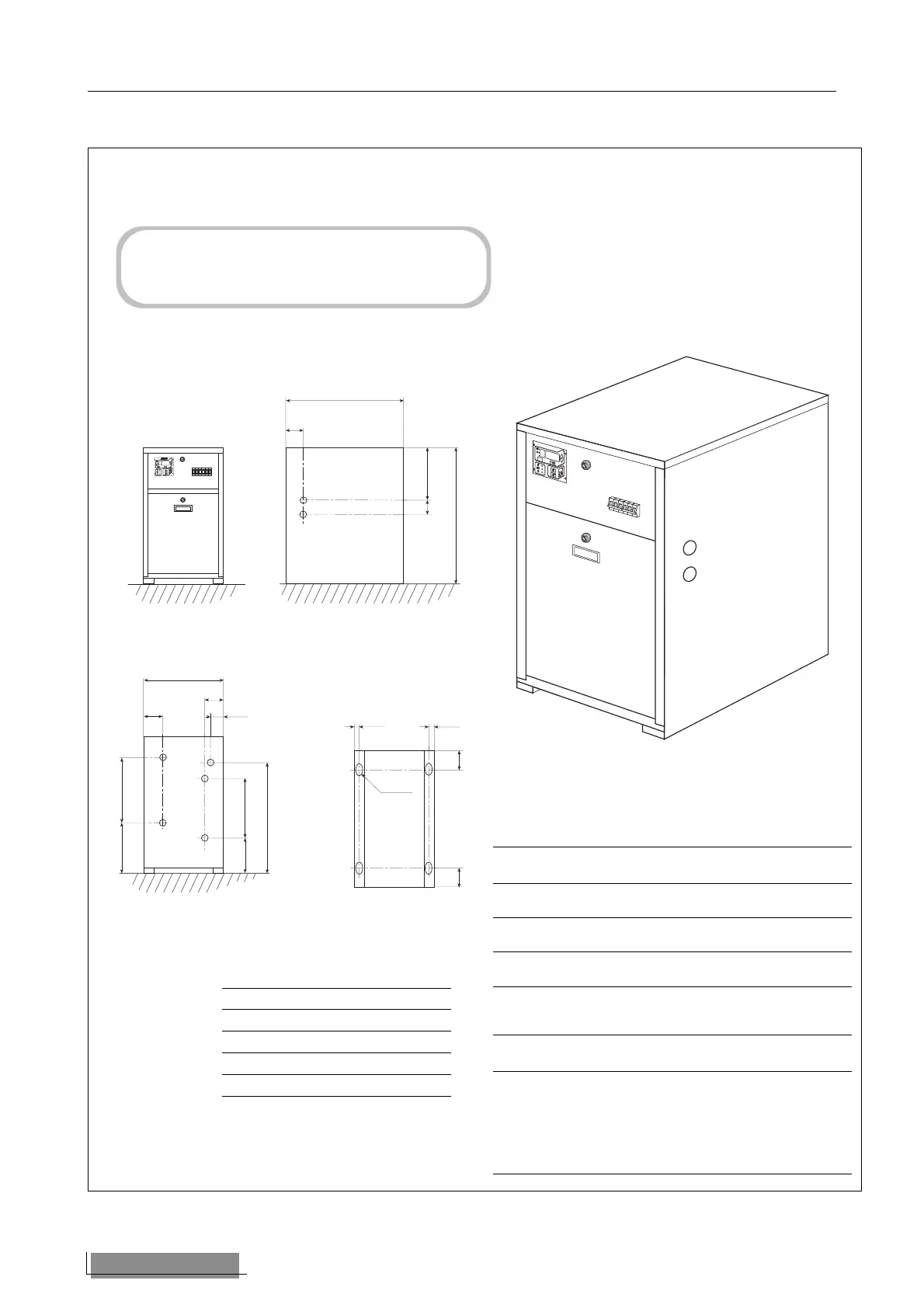
DIMENSIONI • DIMENSIONS (mm)
NRW 57 - 77 - 107 - 127
Mod. A B C
57 850 450 650
77 850 450 650
107 950 450 700
127 950 450 700
Alimentazione acqua • Water supply
NRW NRW-H
F circuito utenze Ingresso Uscita
installation circuit Inlet Outlet
G circuito utenze Uscita Ingresso
installation circuit Outlet Inlet
L circuito esterno Ingresso Uscita
external circuit Inlet Outlet
H circuito esterno Uscita Ingresso
external circuit Outlet Inlet
NRW-E
M = Linea liquido 12,7
Liquid line 12,7
H = Linea gas 12,7 (NRW 57E)
18 (NRW 77E - 107E)
22 (NRW 127E)
Gas line 12,7 (NRW 57E)
18 (NRW 77E - 107E)
22 (NRW 127E)
Gli attacchi idraulici degli NRW sono tutti da 1” Gas
maschio.
NRW hydraulic fittings are all 1” male Gas.
44 Aermec S.p.A.