2321.05 - 6068956_00
NXP 0500 - 1650 2-PIPE SYSTEM / 4-PIPE SYSTEM
EN
CONTROL AND COMMISSIONING
PREPARATION FOR COMMISSIONING
MED WITH NO VOLTAGE PRESENT
Control:
1.
2.
surface.
3. The minimum technical spaces have been
respected.
4. That the main power supply cables have
(see electric
and that the unit has been duly
connected to earth.
5.
made correctly and all the clamps adequately
RIED OUT WHEN THE UNIT IS LIVE.
1. Supply power to the unit by turning the master
will switch on a few seconds after voltage has
been supplied; check that the operating status
2. Check with a tester that the value of the supply
voltage to the phases: single-phase – three-phase
3. Check that the connections made by the installer
are in compliance with the documentation.
4. Verify that the compressor sump resistance/s
is/are operating by measuring the increase in
temperature of the oil pan. The resistance/s must
function for at least 12 hours before start-up of
the compressor and in any event, the tempera-
room temperature.
HYDRAULIC CIRCUIT
1. Check that all hydraulic connections are made
correctly, that the plate indications are complied
with and that a mechanical filter has been
installed at the evaporator inlet (mandatory
component for warranty to be valid).
2. Make sure that the circulation pump/s is/are
operating and that the water flow rate is
sufficient to close the flow switch contact.
3. Check the water flow rate, measuring the
pressure difference between evaporator inlet
and outlet and calculate the flow rate using the
evaporator pressure drop diagram present in
the technical manual (available on the software
selection and on the website www.aermec.com
4. Check correct operation of the flow meters, if
installer – see the chapter of hydraulic circuit to
• Flow switch/Pressure switch: on closing the
cut-off valve at the heat exchanger outlet, the unit
must display the block. Finally, open the valve and
rearm the block.
MACHINE COMMISSIONING
controls have been performed.
- Close the electric control board hatch.
- Starting the unit
WITH THE MACHINE ON, CHECK
COOLING CIRCUIT
CHECK:
- That the compressor input current is lower than the
maximum indicated in the technical data table.
- That in models with three-phase power supply, the
compressor noise level is not abnormal. If this is the
case, invert a phase.
- That the voltage value lies within the pre-fixed limits
larly in correspondence with the manometers pres-
sure transducers and pressure switches pressure
- Overheating
Comparing the temperature read using a contact
thermostat positioned on the compressor intake with
the temperature shown on the low pressure manom-
these two temperatures gives the o v e r -
overheating values are regular, the temperature
measured in the pressing line pipe at the outlet of
sation temperature.
Cooling Only
memory.
Compressor Start-Up Delay
pressor start-ups that are too close.
Minimum time from last switch-off
in Cooling Mode
Minimum time from last switch-on
300 seconds
ATTENTION
Commissioning must be performed with standard settings.
Only when the inspection has been completed can the functio-
Before start-up, power the unit for at least 12-24 hours, posi-
tioning the protection magnet circuit breaker switch and the
Make sure that the control panel is off in order to allow the
compressor oil sump to heat.
2)
track of the interventions performed on the unit.
In this way it will be easy to suitably organise the interventions
making research and the prevention of any
machine breakdowns easier. Use the date to record date, type
measures actuated.
It is forbidden to LOAD the cooling circuit with a refrigerant
different to that indicated. Using a different refrigerant gas can
cause serious damage to the unit.
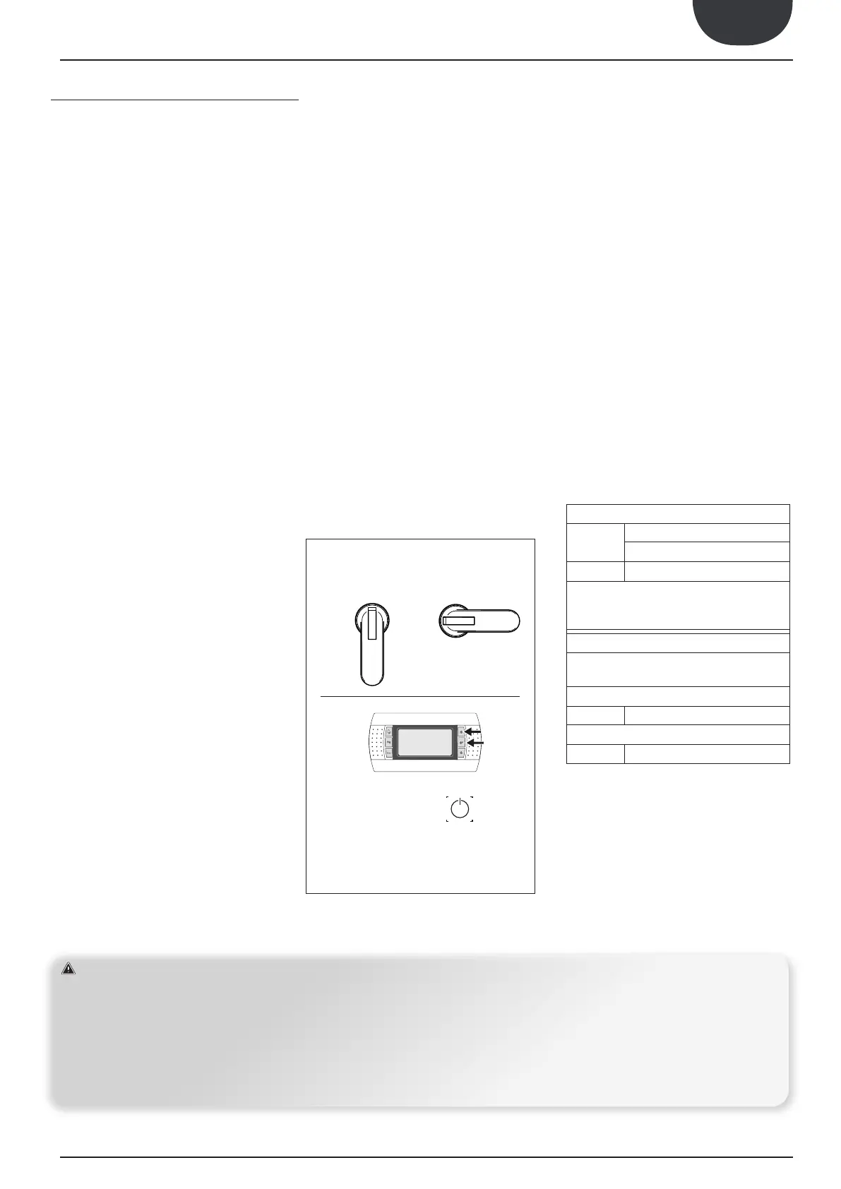
OFFOFF
SELECT MENÙ
ON/OFF
16. CONTROL AND COMMISSIONING


 To Next Page
 Loading...