2521.05 - 6068956_00
NXP 0500 - 1650 2-PIPE SYSTEM / 4-PIPE SYSTEM
EN
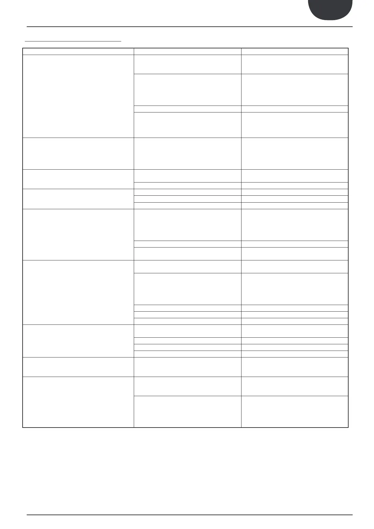
ANOMALY CAUSE REMEDY
The unit does not start
•
• Check the presence of voltage
• Check the safety systems upstream from the appli-
ance
• Master switch at OFF
•
• Control panel at OFF
• Main switch at OFF
• Compressor magnet circuit breaker at OFF
•
• • Check power supply line
• Remote control switch coil broken
• Circuit board broken
•
• Compressor broken
• Replace the component
Insufficient yield
•
• Dirty coils
• Water filter clogged
• Appliance dimensioning
• Operation outside of operational limits
• Check the load and any leaks
• Clean the coils
• Clean the filter
• Check
• Check the operational limits using the graphics
• Liquid return to the compressor
• Inadequate fixing
• Check
• Inverted phase • Invert a phase
• Contacts between metal bodies • Check
• Weak support • Restore
• Loose screws • Tighten the screws
The compressor stops due to intervention
of the protections
• Excessive flow pressure
• Low intake pressure
• Low power supply voltage
• Electric connections fastened badly
• Operation outside of operational limits
• Check the operational limits using the graphics
• • Replace the component
• Circuit breaker protection intervention
• Check power supply voltage
• Check electric isolation of the windings
Compressor high discharge pressure
• High external water temperature
• High utility water inlet temperature
• Check the operational limits using the graphics
• Insufficient air flow
• Insufficient water flow
• Check:
1. Fan operation
2. Cleanliness of the coils
3.
4. Filter cleanliness
• Fan regulation anomalous operation • Check or replace if broken
• Air in the hydraulic system • Bleed the circuit
• Excessive refrigerant gas load • Restore the correct load
Low discharge pressure
• Low external air temperature
• Low inlet water temperature
• Check the operational limits using the graphics, as
above
• Humidity in the cooling circuit • Empty and restore the gas load
• Air in the hydraulic system • Bleed the circuit
• Insufficient gas load • Restore the correct load
High intake pressure
• High external air temperature
• High utility inlet water temperature
• Thermostatic expansion valve too open or damaged
• Check the operational limits using the graphics
• Adjust or replace if damaged
Low intake pressure
• Low utility water inlet temperature
• Low external water inlet temperature
• Thermostatic expansion valve damaged or blocked
• Check the operational limits using the graphics
• Adjust or replace if damaged
• Insufficient water flow
• Insufficient air flow
• Check:
1. Fan operation
2. Cleanliness of the coils
3.
4. Filter cleanliness
TROUBLE SHOOTING
19. TROUBLE SHOOTING



 To Next Page