12
DIAMETER OF THE HYDRAULIC CONNECTIONS
AERAULIC CONNECTIONS
ELECTRICAL CONNECTIONS
INTERNAL COIL (W) EXTERNAL PROMISCUOUS COIL (MBF and MBF_X) EXTERNAL POST HEATING COIL (MBP)
Type Ø M coil inlet
connections
Ø M coil outlet
connections
Ø M conden-
sate drain
connections
Type Ø M coil inlet
connections
Ø M coil outlet
connections
Ø M conden-
sate drain
connections
Type Ø M coil inlet
connections
Ø M coil outlet
connections
030 H/C 1/2” 1/2” 1/2” - - - - Post-Heating 1/2” 1/2”
050 H/C 1/2” 1/2” 1/2” - - - - Post-Heating 1/2” 1/2”
070 H/C 1/2” 1/2” 1/2” - - - - Post-Heating 1/2” 1/2”
100 H/C 1/2” 1/2” 1/2” - - - - Post-Heating 1/2” 1/2”
140 Hot 3/4” 3/4” 1” H/C 3/4” 3/4” 1” Post-Heating 1/2” 1/2”
200 Hot 1” 1” 1” H/C 3/4” 3/4” 1” Post-Heating 1/2” 1/2”
300 Hot 1” 1” 1” H/C 1” 1” 1” Post-Heating 3/4” 3/4”
400 Hot 1” 1” 1” H/C 1” 1” 1” Post-Heating 3/4” 3/4”
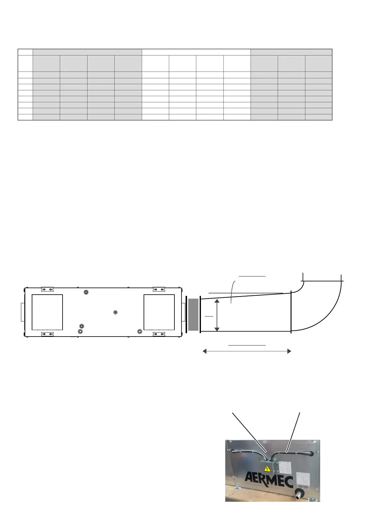
MAX 7°
MIN 2.5 A
A
GENERAL STANDARDS
• prepare adequate brackeng to support the ducts so that the unit does not bear their weight
• connect the ow and recovery vents to the ducts placing an-vibraon joints in between (oponal)
• provide an earth cable acng as a bridge on the an-vibraon joint to guarantee electrical equipotenality between the duct and the unit
• provide, before bends and branches, the ow duct with a straight secon measuring at least 2.5 mes the smallest side of the duct to prevent loss
of fan performance
• make sure that the slope of the ducng branching secons does not exceed 7°.
GENERAL STANDARDS