36
F = Fusibile • Fuse • Fusible
Sicherung • Fusible
IG = Interruttore generale • Main switch
Interupteur général • Hauptschalter
Interruptor general
C = Comune • Common • Commun
Ph1 Durchschaltleitung • Común
M = Velocità Media • Medium speed
Vitesse moyenne • Mittlere Geschwindigkeit
Velocidad media
L = Velocità minima • Minimum speed
Vitesse minimum • Mindestgeschwindigkeit
Velocidad mínima
H = Velocità massima • maximum speed
Vitesse maximum • Maximale Geschwindigkeit
Velocidad máxima
N = Neutro • Neutral • Neutre • Neutral • Neutro
MV = Motore ventilatore • Fan motor
Moteur ventilateur • Ventilatormotor
Motor del ventilador
PE = Collegamento a terra • Earth connection
GND Mise à terre • Erdanschluss • Toma de tierra
PH = Linea • Line • Ligne• Leitung • Línea
SA = Sonda ambiente • Room sensor
Sonde ambiante • Raumtemperaturfuhler
Sonda ambiente
SC = Scheda di controllo
Electronic control board
Platine de contrôle • Steuerschaltkreis
Tarjeta electrónica de control
SW = Sonda minima temperatura acqua
Water low temperature sensor
Sonde minimum temp. eau
Wasserfühler
Sonda temperatura mínima del agua
= Collegamenti da eseguire in loco
On-site wiring
Raccordements à effectuer in situ
Vor Ort auszuführende Anschlüsse
Cableado in situ
AR = Arancio • Orange • Orange • Orange • Naranja
BI = Bianco • White • Blanc • Weiss • Blanco
BL = Blu • Blue • Bleu • Blau • Azul
GR = Grigio • Grey • Gris • Gray • Gris
MA = Marrone • Brown • Marron • Braun • Marrón
NE = Nero • Black • Noir • Schwarz • Negro
RO = Rosso • Red • Rouge • Rot • Rojo
VE = Verde • Green • Vert • Grün • Verde
VI = Viola • Violet • Violet • Violet • Violeta
YG = Giallo-Verde • Yellow-Green • Jaune-Vert
Gelb-Grün • Amarillo-Verde
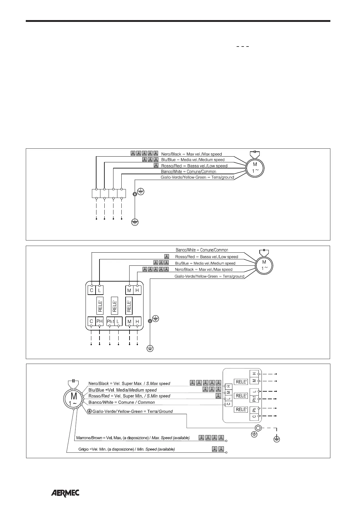
LEGENDA • READING KEY • LEGENDE • LEGENDE • LEYENDA
SCHEMI ELETTRICI • WIRING DIAGRAMS • SCHEMAS ELECTRIQUES • SCHALTPLÄNE • ESQUEMAS ELÉCTRICOS
Gli schemi elettrici sono soggetti ad un continuo aggiornamento, è obbligatorio quindi fare riferimento a quelli a bordo macchina.
All wiring diagrams are constantly updated. Please refer to the ones supplied with the unit.
Nos schémas électriques étant constamment mis à jour, il faut absolument se référer à ceux fournis à bord de nos appareils.
Die Schaltpläne werden ständig aktualisiert, deswegen muss man sich stets auf das mit dem Gerät gelieferte Schaltschema beziehen.
El cableado de las máquinas es sometido a actualizaciones constantes. Por favor, para cada unidad hagan referencia a los esquemas suministrados con la misma.
YG
BI
RO
BL
NE
230V ~ 50Hz
V1
(PH)
V2
(PH)
V3
(PH)
NPH
N
TS 23
TS 34 - TS 36
TS 43 - TS 46
TS 53 - TS 56
TS 63
TS 74 - TS 76
230V ~ 50Hz
V1 (PH)
V2 (PH)
V3 (PH)
N
PH
N
YG
BI
RO
BL
NE
MA
GR
TS 63 5V
TS 74 5V
TS 76 5V
YG
BI
RO
BL
NE
230V ~ 50Hz
V1
(PH)
V2
(PH)
V3
(PH)
N
1
N
32
TS 13
TS 16
 Loading...