11
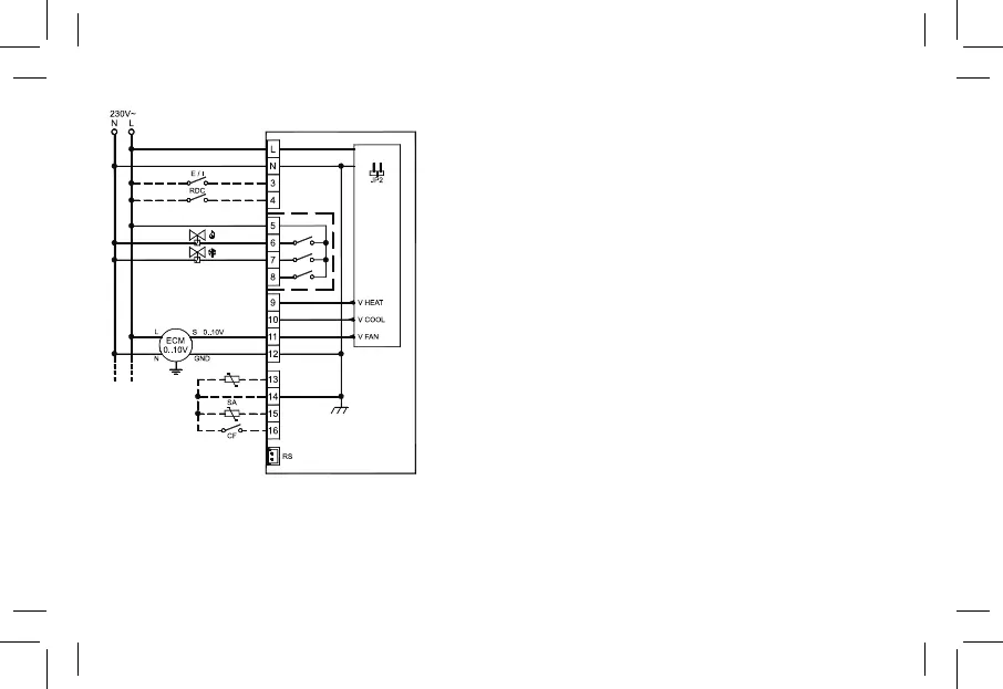
Fig. 8: Schema di collegamento per pilotaggio di due attuatori on/off a 230V~ per impianto a 4 tubi e pilotaggio proporzionale del ventilatore.
Wiring diagram for 2 on/off 230V~ actuators in 4 pipes system and proportional fan drive.
Schéma de connexion pour pilotage de deux actuateurs on/off à 230V~ pour installation à 4 tubes et pilotage proportionnel du ventilateur.
Esquema de conexión para el pilotaje de dos actuadores on/off a 230V~ para instalación a 4 tubos y pilotaje prporcional del ventilador.
Abb. 8: Verbindungsschema für die Steuerung der beiden Aktuatoren on/off mit 230V~ pro Anlage mit 4 Rohren und proportionaler Steuerung.
Nel caso di impianto a 2 tubi con un solo attuatore on/off, esso dovrà essere
collegato sul morsetto 6.
In case of 2 pipes system with single on/off actuator, it must be wired at
terminal 6.
Im Falle einer Anlage mit 2 Rohren mit einem einzigen Aktuator on/off, muss
dieser auf der Klemme 6 angeschlossen werden.
Dans le cas d’installation à 2 tubes avec un seul actuateur on/off, celui-ci devra
être connecté sur la borne 6.
Si la instalación es a 2 tubos un sólo actuador on/off, este deberá conectarse
al borne 6.
P01: 1
P05: 0 (1)
P06: 2 (3)
P07: 2 (3)
SW